Chapter 4 – Start-up Procedure
ACH 400 with Electronic Bypass User’s Manual 4-3
Relay Output Jumpers A Motor Run relay contact output is provided at terminals X2:18 and X2:19
for external indication of the motor status. The output consists of a normally
open Drive Run contact and a normally open Bypass Run contact. The two
contacts are connected in parallel so that a contact closure is provided
whenever the motor is running. The Drive Run and Bypass Run contacts can
be separated and used individually by cutting jumpers R63 and R64 on the
bypass control board. See Figure 3-4 in Chapter 3.
Overload Trip
Current Adjustment
Potentiometer
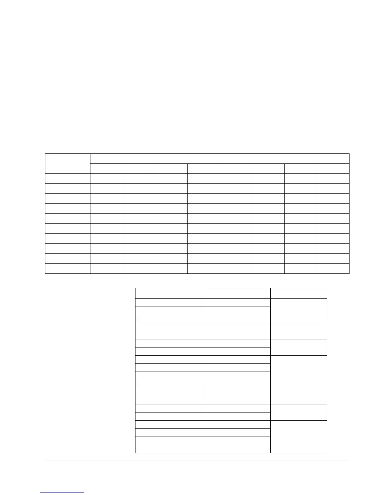
The overload protection trip current must be adjusted to the motor nameplate
current using the adjustment potentiometer located in the lower right hand
area of the bypass control board as shown in Figure 4-1. Table 4-2 shows the
trip currents for the various frame sizes for potentiometer settings for 0 to 100.
Table 4-2 Overload Trip Current Potentiometer Settings
Table 4-3 Overload Trip Current DIP Switch Code Selection
Potentiometer
Setting
Trip Currents for the Various Potentiometer Settings
ABCDEFGH
10
1.2 2.5 3.8 7.5 10.4 15.5 20.0 47.7
20
2.4 5.0 7.6 15.020.831.040.095.4
30
3.6 7.5 11.4 22.5 31.2 46.5 60.0 143.1
40
4.8 10.0 15.2 30.0 41.6 62.0 80.0 190.8
50
6.0 12.5 19.0 37.5 52.0 77.5 100.0 238.5
60
7.2 15.0 22.8 45.0 62.4 93.0 120.0 286.2
70
8.4 17.5 26.6 52.5 72.8 108.5 140.0 333.9
80
9.6 20.0 30.4 60.0 83.2 124.0 160.0 381.6
90
10.8 22.5 34.2 67.5 93.6 139.5 180.0 429.3
100
12.0 25 38.0 75.0 104.0 155.0 200.0 477.0
208 - 240 VAC 308 - 480 VAC Switch Code
ACH401x0042x ACH401x0043x
AACH401x0053x
ACH401x0063x
ACH401x0052x ACH401x0093x
B
ACH401x0062x ACH401x0113x
ACH401x0163x
C
ACH401x0203x
ACH401x0112x ACH401x0253x
DACH401x0162x ACH401x0303x
ACH401x0202x ACH401x0413x
ACH401x0302x ACH40160603x E
ACH401x0412x ACH40160703x
F
ACH40160601x ACH40161003x
ACH40160701x ACH40x61203x
G
ACH40x61403x
ACH40262103x
H
ACH40262603x
ACH40263203x
ACH40264003x
 Loading...


