CHAPTER 6 – ELECTRICAL INSTALLATION 81
6.7 Cables between integrated
transformer and drive
Cabling between drive and integrated transformer includes the
following connections:
• Transformer primary and secondary cables
• Temperature sensor cables
• Three-phase power supply cable and control
cable to each of the transformer fan units
• Air filter and pressure monitoring cable
•Heating cable (option)
The cables are identified by their specific number
and are labeled with the designation of the termi-
nal where they are connected to.
The terminals for the primary (6-3: 4) and the sec-
ondary cables (6-3: 5) are located on the side wall
of the transformer cabinet. The terminals are
accessible through cutouts in the terminal com-
partment of the drive. The power supply and con-
trol cables of the transformer’s fan units are
routed through the cable lead-through (6-3: 3) on
the side wall.
For further information, see the applica-
ble wiring diagrams.
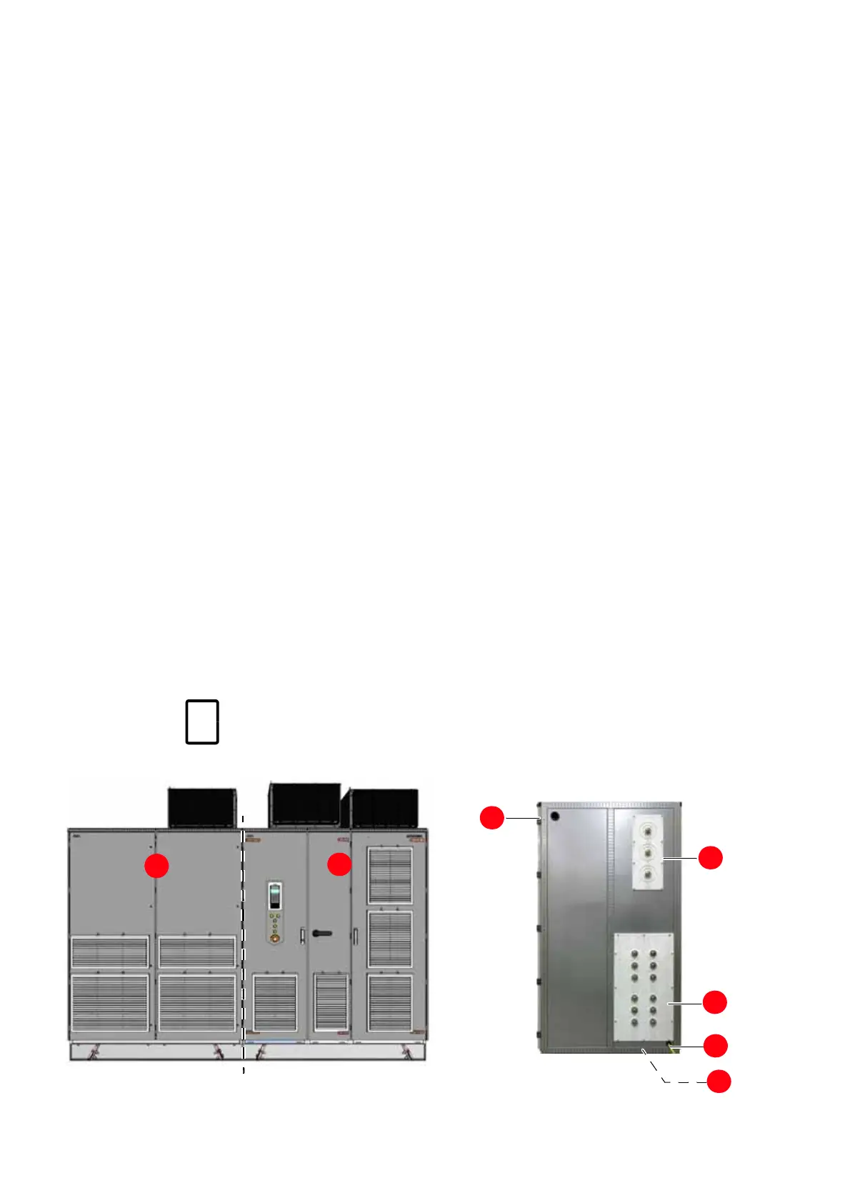
6-3 Drive with integrated
transformer
Front view
Side view
1. Input transformer
2. Drive
3. Control cable lead-through
4. Terminals for primary cables
5. Terminals for secondary cables
6. Grounding cable
7. Heating cable (optional)
1
2
3
4
5
6
7

 Loading...


