CHAPTER 6 – ELECTRICAL INSTALLATION 87
6.10 Auxiliary power, control and
serial communication cables
The method to prepare the auxiliary power and control cables for
connection is described below.
6.10.1 Further information
The power feed for the auxiliary
supply must be protected with a
suitable circuit protection rated
for the inrush current. For infor-
mation, see utility consumption
list of the drive.
6.10.2 Preparing the cable entry and the cables
Determining the cable length
1. Determine the required length of a cable
between the point of entry and the connection
point inside the cabinet.
2. Cut the cable to the required length before con-
nection.
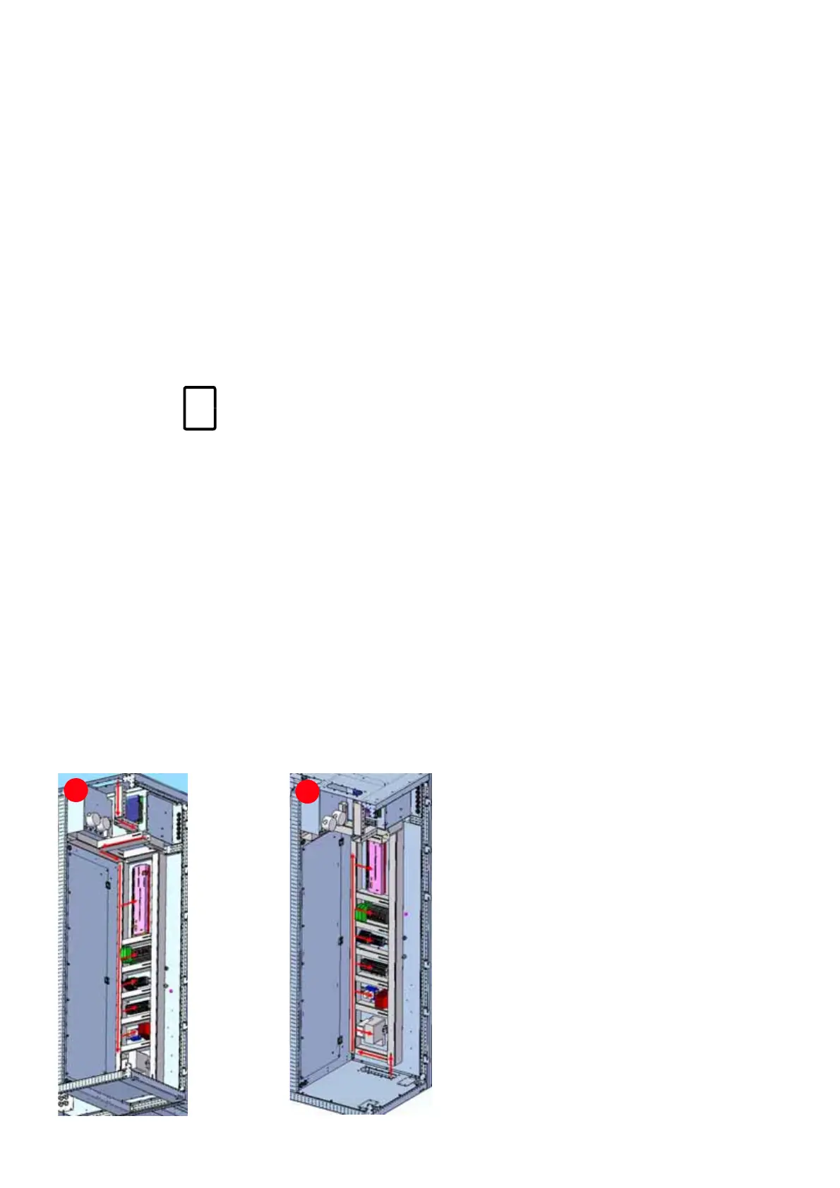
Routing the cables
Route the cables to the customer terminals in the
control compartment as illustrated.
Preparing the cables for EMC plates
Top entry
1. Remove the grommets.
See mechanical drawings for information
on:
• Project-specific cable entry
• Dimensions between point of cable
entry and terminals
See wiring diagrams for information on:
• Conventions for cross-references and
device identification
• Terminal designations
6-8
(1): Top-entry (2): Bottom-entry
1
2

 Loading...


