Installation 17
Example wiring diagrams
Connect the cables as shown in the diagram below. For more information on the
components, see chapter Technical data.
STO connections without safety relays
The following diagrams show the STO connections without safety relays in:
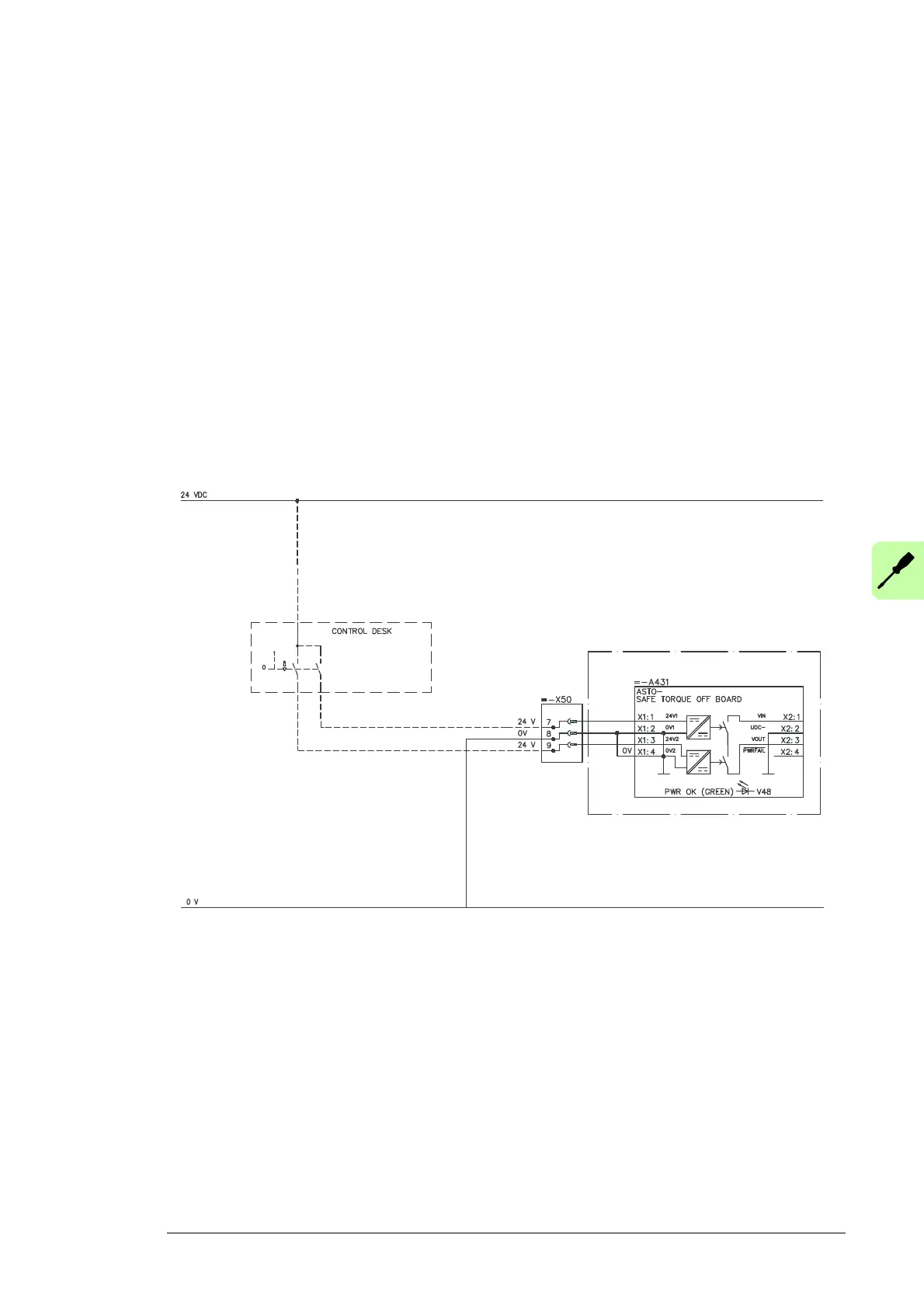
• connecting an emergency stop push button to the drive/inverter module without safety
relay (page 22).
• single drives R2-R6 and R7-R8 (page 18)
• inverter modules R2i-R4i, R5i, R7i, R8i, R7iLC and R8iLC (pages 19-21)
Connecting the STO activation switch
We recommend using a safety relay between the activation switch and the STO input,
because the STO is not capable of detecting any redundancy fault of the switch (such as a
welded contact).
INVERTER MODULE R8i
3AUA0000096631

 Loading...


