12 Implementing a Safe disconnection function
Two-channel connection to drive STO terminals
General
This section describes an implementation of the ATEX-compliant motor thermal protection
circuit. The circuit uses the ATEX-certified Safe disconnection function (option +Q971) of
the drive and a two-channel (redundant) connection to the drive STO terminals.
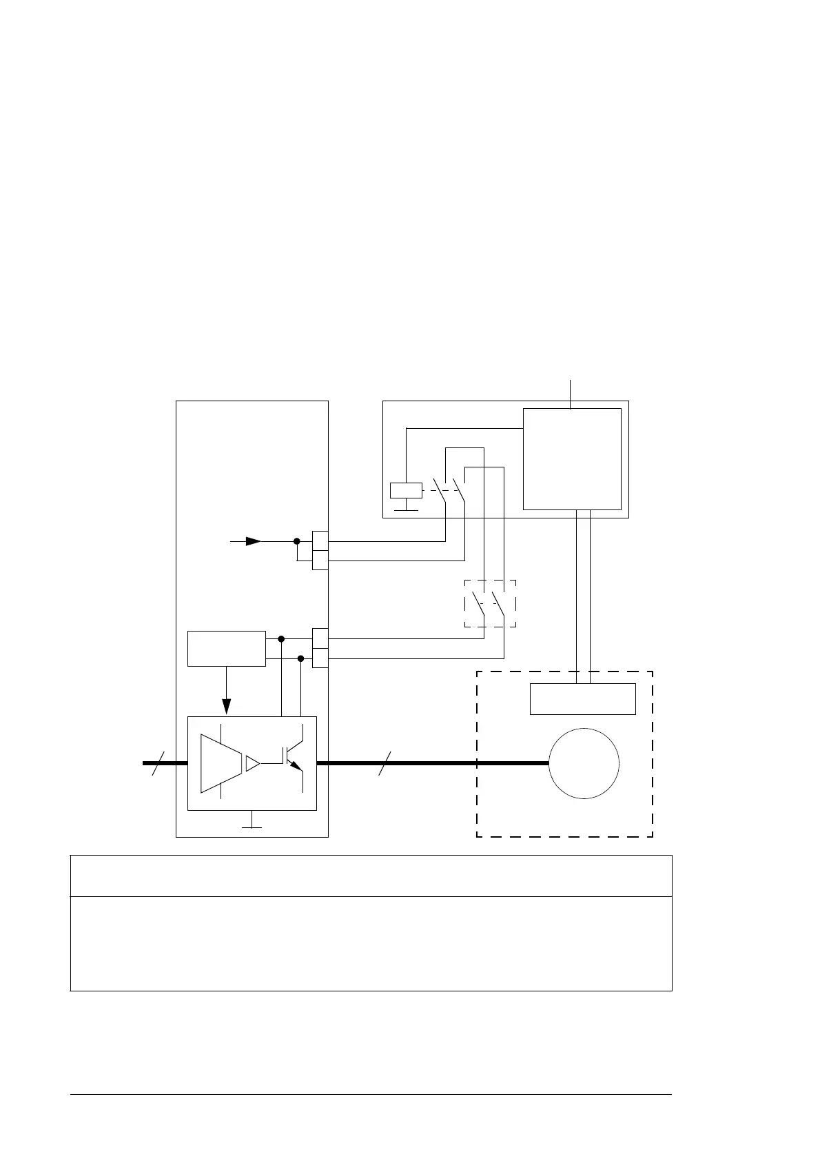
Connection diagram
The diagram below shows the connections. The system integrator must acquire the
components and do the installation drawn outside the drive border line.
The output contacts of the protective relay can be connected in series with another Safe
torque off activation switch/relay (if present).
1)
An ATEX-compliant protective relay. The relay monitors a sensor circuit, and activates the Safe torque off
function of the drive by opening the control circuits when necessary.
2)
You can use the drive STO function for several external safety functions at the same time (for example,
ATEX-compliant thermal motor protection, and emergency stop). If you do, you must connect the STO
activation switches or relays used in other safety functions in series with the ATEX-compliant protective
relay.
When you install the equipment, make sure that you maintain redundancy (separation) of switching signals.
+24 V
Control
circuit
Drive
2)
Safe torque off
activation switch or relay
(open = active)
33
3
~
Ex
motor
3
~
supply
1)
Protective relay
Control
circuit
Control voltage
Sensor
Potentially explosive
atmosphere
XSTO
XSTO
1
2
3
4

 Loading...