14 Implementing a Safe disconnection function
Connection diagram
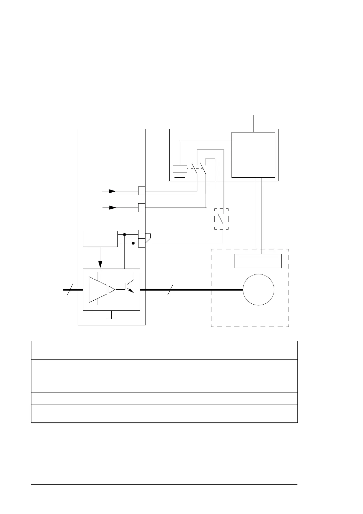
The diagram below shows the connections. The system integrator must acquire the
components and do the installations drawn outside the drive border line.
The output contact of the protective relay can be connected in series with another Safe
torque off activation switch/relay (if present).
When you install the equipment, make sure that you maintain separation of the switching
(safety) signal with any other signals.
1)
An ATEX-compliant protective relay. The relay monitors a sensor circuit, and activates the Safe torque off
function of the drive by opening the control circuits when necessary.
2)
You can use the drive STO function for several external safety functions at the same time (for example,
ATEX-compliant thermal motor protection, and emergency stop). If you do, you must connect the STO
activation switches or relays used in other safety functions in series with the ATEX-complaint protective
relay.
3)
Connected to a digital input on the control board for the protection relay status indication.
4)
The STO function of the drive must always have redundant connection. Connect the XSTO terminals 3
and 4 in accordance with the above figure.
+24 V
Control
circuit
ACS850
2)
Safe torque off
activation switch or relay
(open = active)
33
3
~
Ex
motor
3
~
supply
Protective relay
1)
Control
circuit
Control voltage
Sensor
Potentially explosive
atmosphere
XSTO
XSTO
1
3
4
XDI
3)
4)
1
+24 V
XD24

 Loading...