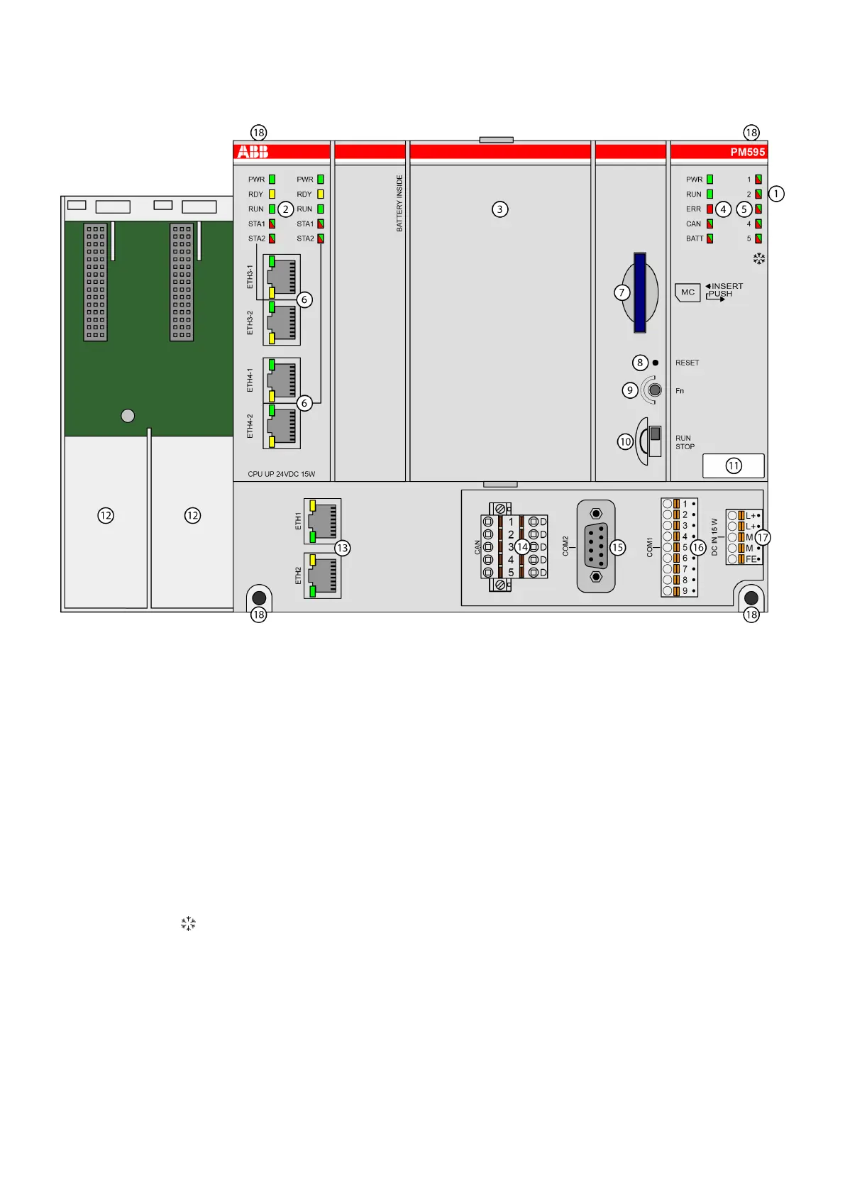
28.4 Connection
1 I/O bus for connection of I/O modules
2 2x 5 LEDs to display the states of the fieldbuses
3 Cover for battery and display
4 5 LEDs to display the states of the processor module
5 5 LEDs (reserved)
6 2x2 RJ45 interfaces for fieldbuses
7 Slot for memory card
8 Reset button
9 Button (reserved)
10 RUN/STOP switch
11 Label
12 Slots for communication modules (max 2; unused slots must be covered with TA524)
13 2 RJ45 interfaces for Ethernet connection
14 5-pin terminal block (reserved)
15 Serial interface COM2 (D-sub 9)
16 Serial interface COM1 (9-pin terminal block, removable)
17 Power supply (5-pin terminal block, removable)
18 4 holes for wall mounting
Sign for XC version
2019/11/15 3ADR024117M02xx, 11, en_US 219
 Loading...
