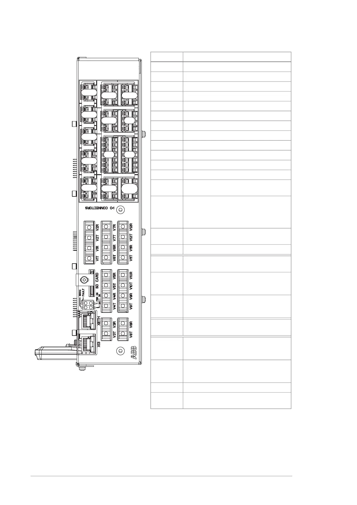
Description
Analog inputsXAI
Analog outputsXAO
Digital inputs, Digital input interlock (DIIL)XDI
Digital input/outputsXDIO
Drive-to-drive linkXD2D
+24 V output (for digital inputs)XD24
Ethernet port – Not in useXETH
External power inputXPOW
Relay output RO1XRO1
Relay output RO2XRO2
Relay output RO3XRO3
Safe torque off connection (input signals)XSTO
Safe torque off connection (to inverter
modules)
XSTO OUT
(On the opposite side) Connection for FSO
safety functions module (optional)
Note: The FSO safety functions module
can be used only with ACS880 inverters.
X12
Control panel, PC connection through the
control panel
X13
Not in use by defaultX485
Fiber optic connection to modules 1 and 2
(VxT = transmitter, VxR = receiver)
V1T/V1R,
V2T/V2R
Fiber optic connection to modules 3…7
(BCU-12 and BCU-22 only)
(VxT = transmitter, VxR = receiver)
V3T/V3R
…
V7T/V7R
Fiber optic connection to modules 8…12
(BCU-22 only)
(VxT = transmitter, VxR = receiver)
V8T/V8R
…
V12T/V12R
Data logger memory card for inverter
module communication
SD CARD
Real-time clock battery voltage is higher
than 2.8 V. If the LED is off when the con-
trol unit is powered, replace the battery.
BATT OK
The control program has generated a fault.
See the firmware manual of the supply/in-
verter unit.
FAULT
Internal voltage is sufficientPWR OK
Writing to memory card in progress. Do
not remove the memory card.
WRITE
XDI
XSTO
X485
XD2D
XRO1
XRO2
XRO3
XDIO
XD24
XSTO
OUT
XAI
XAO
XPOW
14 Operation principle and hardware description

 Loading...


