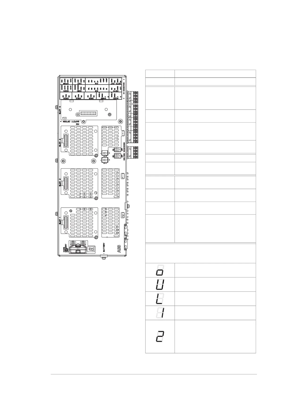
Layout
The figures show the layout of the control unit. For the default I/O connection diagrams
and more information on the connections, refer to the converter hardware manual.
Description
I/O terminals (see following diagram)I/O
I/O extension, encoder interface or
fieldbus adapter module connection.
(This is the sole location for an FDPI-02
diagnostics and panel interface.)
SLOT 1
I/O extension, encoder interface or
fieldbus adapter module connection
SLOT 2
I/O extension, encoder interface, field-
bus adapter or FSO safety functions
module connection
SLOT 3
RDCO DDCS communication option
module connection
SLOT 4
Memory unit connectionX205
Holder for real-time clock battery
(BR2032)
BATTERY
Mode selector for analog input AI1 (I =
current, U = voltage)
AI1
Mode selector for analog input AI2 (I =
current, U = voltage)
AI2
Termination switch for drive-to-drive link
(D2D)
D2D TERM
Ground selection. Determines whether
DICOM is separated from DIOGND (ie.
the common reference for the digital in-
puts floats). See the ground isolation
diagram.
DICOM=
DIOGND
7-segment display
Multicharacter indications are displayed as repeated
sequences of characters
(“U” is indicated briefly before “o”.)
Control program running
Control program startup in progress
(Flashing) Firmware cannot be started.
Memory unit missing or corrupted
Firmware download from PC to control
unit in progress
At power-up, the display may show short
indications of eg. “1”, “2”, “b” or “U”.
These are normal indications immedi-
ately after power-up. If the display ends
up showing any other value than those
described, it indicates a hardware failure.
Operation principle and hardware description 13

 Loading...


