Installing I/O extension, fieldbus adapter and pulse
encoder interface modules
WARNING
Obey the safety instructions of the drive. If you ignore them,
injury or death, or damage to the equipment can occur. If you are not a qualified
electrical professional, do not do installation, commissioning or maintenance
work.
NOTICE
Use ESD wristband when you handle printed circuit boards. Do not touch
the boards unnecessarily. The boards are sensitive to electrostatic discharge.
Pay attention to the free space required by the cabling or terminals coming to the
option modules.
1. Stop the drive and do the steps in section Electrical safety precautions of the
converter hardware manual.
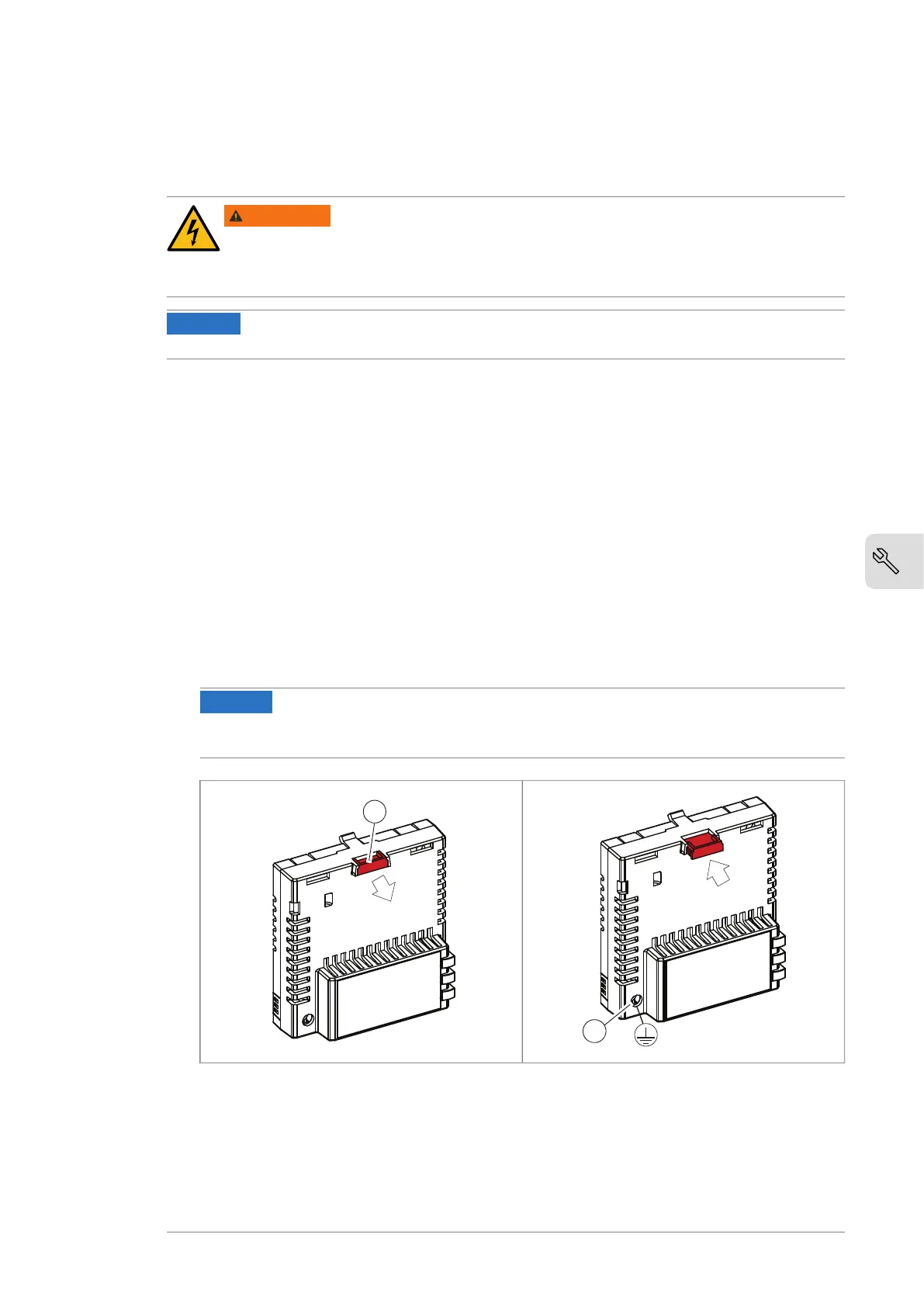
2. Pull out the lock (a) with a screw driver.
Note: The location of the lock depends on the module type.
3. Install the module to a free option module slot on the control unit.
4. Push in the lock (a).
5. Tighten the grounding screw (b) to a torque of 0.8 N·m (7 lbf·in).
Note: The screw tightens the connections and grounds the module. It is essential
for fulfilling the EMC requirements and for proper operation of the module.
NOTICE
Do not use excessive force, or leave the screw too loose. Over-tightening
can cause damage to the screw or module. A loose screw can cause an operation
failure.
6. Connect the wiring to the module. Obey the instructions given in the
documentation of the module.
If you must remove the option module after it is installed into the drive, use a suitable
tool (for example, small pliers) to carefully pull out the lock.
Mechanical installation 21

 Loading...


