Specification of Variants and Options
Product Specification IRB 4400 M98A/BaseWare OS 3.2 55
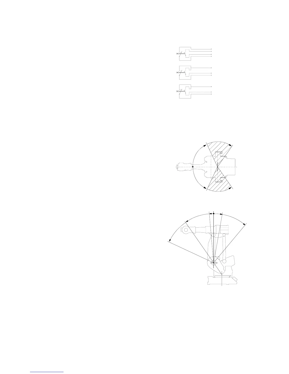
071- The signals are connected to 12-pole screw terminals, Phoenix MSTB 2.5/12-ST-5.08,
074 in the controller (see Figure 33).
081 1 switch, axis 1
082 2 switches, axis 1
083 3 switches, axis 1
Figure 33 Connections of the switches.
WORKING RANGE LIMIT
To increase the safety of the robot, the working range of axes 1, 2 and 3 can be restricted.
621 Axis 1
Two extra stops for restricting the working
range.The stops can be mounted within the area
from 65
o
to 125
o
. See Figure 34.
Figure 34
622 Axis 2
Stop lugs for restricting the working range.
Figure 35 illustrates the mounting positions
of the stops.
Note! 5
o
is not valid for 4400FS.
Figure 35
623 Axis 3
Equipment for electrically restricting the working range in increments of 5
o
.
Controller
Controller
Controller
The first
switch
The second
switch
The third
switch
125
o
65
o
65
o
125
o
65
o
35
o
5
o
10
o
40
o

 Loading...


