PowerValue
Normal Battery Bypass Fault
10 11 12
2 4 5 6 7 8 91 3
13
—
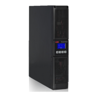
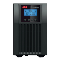
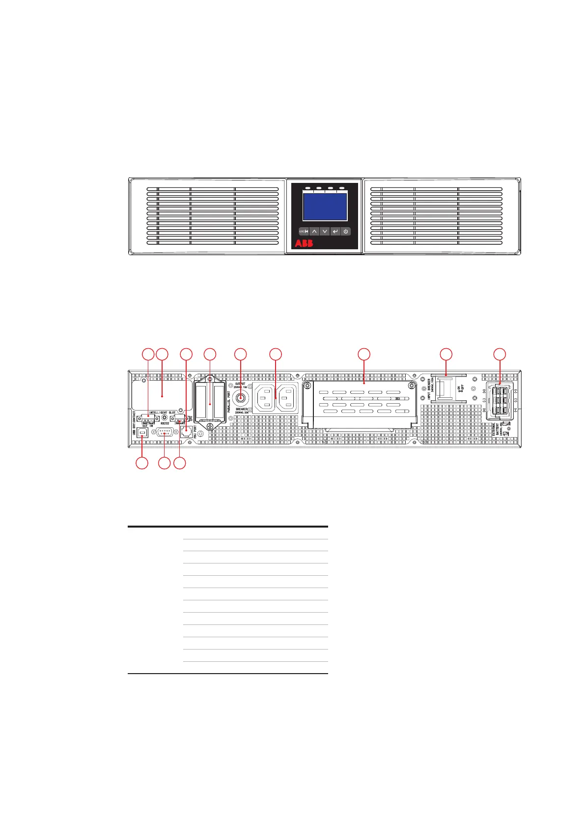
08 UPS front panel
—
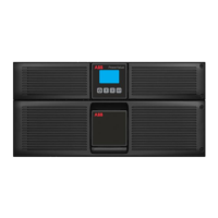
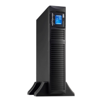
09 UPS rear view
3.3.1 UPS front panel
Figure 8 shows the front panel of the UPS.
3.3.2 UPS rear panel
Table 2 and Figures 9, and Table 3 and Figure 10
show the connectors and ports in the UPS and
external battery module rear panel.
—
3.3 General characteristics
—
09
—
08
—
Table 2: UPS rear panel connectors and ports
1 Dry IN/OUT
2 SNMP/ AS400 slot
3 RJ11 (PDU connection)
4 Parallel card
5 Output breaker
6 Output socket
7 Input/Output terminals
8 Input breaker
9 EBM connector
10 USB
11 RS232
12 EPO
3 INSTALL ATION
 Loading...