Section 5 1MAC303209-MB C
Connecting
20 620 series
Installation Manual
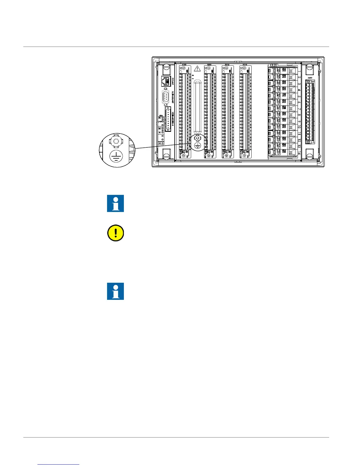
Figure 8: The protective earth screw is located between connectors X100 and
X105
2. Connect the ground lead to the ground bar.
Use either stripped wire screwed between a washer cup and the protective ground
screw or a ring-lug.
3. Tighten the protective ground screw.
4. Support the ground lead so that it cannot break or weaken.
Be aware of the mechanical, chemical and electrochemical environment.
5.4 Connecting analog signals
A connection diagram is needed to connect the analog signals.
When using the ring-lug type for CT terminals.
1. Remove the fixing screw.
2. Slide the screw through the terminal lug and screw it back on.
The ground lead should be as short as possible but notice that extra length
is required for door mounting.
Each IED must have its own ground lead connected to the ground circuit
connector.
Select a suitable ring-lug to fit under the M4 screw.

 Loading...


