Connections and Settings
Communication Unit 560CMD11
Doc.-No.: 1KGT 150 765 V005 1 3
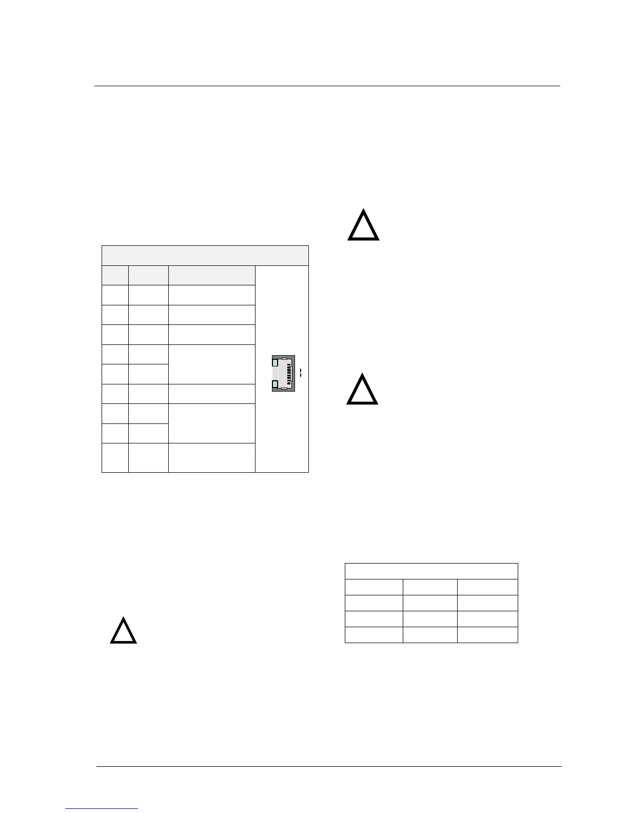
Ethernet Interface E1 and E2
The Ethernet Interfaces are available on a RJ45
connector and supports different functions:
Webserver-diagnostic with download of
configuration files and firmware
TCP/IP based protocols
Integrated HMI
The signals are used according to Table 3.
RJ45
1
8
Lnk
Act
RJ45
1
8
RJ45
1
8
Lnk
Act
Table 3: Ethernet Interfaces E1, E2
IO-Bus
The connection to the local I/O boards is done by
a 20 pole female connector. The connection to the
serial peripheral bus (Wired OR-Bus, (WOR)) is
done by a 20 pole male connector (see Fig. 6).
The order of the 23AD62 module includes one
ribbon cable. The ribbon cable should not exceed
a length of 50cm (20inch).
Power Supply DC- In
The supply voltage for the 560CMD11 is 24VDC.
The connector consists of a 3 pole pluggable
screw-terminal 5,08mm (see Tab.4 and Fig. 8 or
Fig. 11).The max. input power is 67 Watt.
In some cases an external potential
isolation for the DC-Input is neces-
sary. This can be done e.g. by a
power supply unit 560PSU40/41.
Power Supply DC- Out
The 560CMD11 provides 24VDC output power for
max. 0.5A.The connector consists of a 3 pole
pluggable screw-terminal 5,08mm (see Tab. 4 and
Fig. 8 or Fig. 11).The output power can only be
used for the relay output board (23BO61/62).
560CMD11 Earthing
On the strength of safety and EMC protection it is
important to make a connection as short as possi-
ble to a system earth (may be DIN-rail or mount-
ing plate). An ordinary 1.5mm
2
multi-core wire
(green/yellow) can be used and should not ex-
ceed a length of 100 cm (39 inch). The first pin of
the 3 pole DC-In connector is the earth-pin (see
Tab. 4 and Fig. 8 or Fig. 11).
Table 4: 3 Pole Power Connector
Attention: It is not allowed to pull
or to plug the 20 pole ribbon ca-
ble during the operation pro-
cess.
It is not allowed to use the output
power for the process supply!

 Loading...