Doc.-No.: 1KGT 150 765 V005 1 4
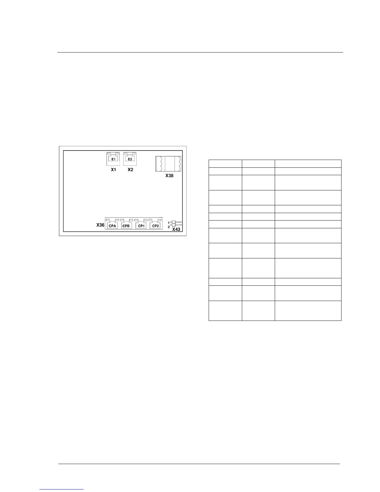
The power supply terminal X38-2 (-) is internal
connected with the housing ground by terminal
X43 (see Fig. 3).
The protection earth must be connected to screw
terminal 4-1 (see Tab. 4) for both 560CMD11 re-
visions. In rare cases (e.g. when grounding signal
zero to Vin (+)) the jumper X43 has to be re-
moved, but it is only possible in Version R0001.
Opening of the housing is done in the same way
as for changing the CF card.
Fig. 3: Placement of X43 at CMU PCB
Additional information for R0011
It should be noted, that the module stipulates a
minus earthing concept conditional on the GPRS
technologies. In system with other earth concept it
must be used a galvanic isolated power supply for
the CMD11 to avoid the destroying (see Fig.4).
Depending of the system architecture may also be
required an additional galvanic isolated RS232
interface (see Fig.5), if the entire system is
grounded positively.
Signaling
The red LED of the 560CMD11 is controlled by
the RTU560 firmware. For the definition and oper-
ation of the LED “ERR" please refer to the release
specific function description. The connector em-
bedded LEDs “Tx” and “Rx” are directly connected
to the receiver/transmitter of the communication
line. The LEDs “Act" and “Lnk” are directly con-
nected to the Ethernet-controller.
Tab. 5 describes the system LEDs of the
560CMD11.

 Loading...