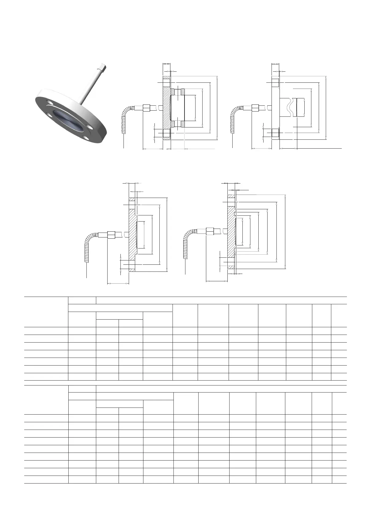
5.5 Fixed flange diaphragm seals – flush and extended (S26FA, S26FE)
These diaphragm seal are designed to connect to flanged pipe fitting, according to ASME or EN standards. For liquid level
measurement installations, the seal connects to a flanged tank nozzle, compliant to relevant standard. The sealing is provided by a
selectable gasket seat surface finish. The “fixed” mounting flange is integral with the seal.
Ø A
Ø B
Ø E
134 (5.3)
Ø D
Ø C
25 (0.98) for 1/4 NPT
33 (1.30) for 1/2 NPT
flushing threads
F
G
134 (5.3)
Ø B
Ø I
Ø H
F
L
3 (0.12)
Ø E
Ø C
Ø A
Ø D
Ø D
Ø B
Ø C
F
G
Ø E
134 (5.3)
Ø A
EN 1092-1 Form E EN 1092-1 Form D
ASME and EN 1092-1 smooth and Form B1 (flushing ring as option, only for flush version)
Ø B
Ø E
134 (5.3)
Ø D
Ø C
F
G
Ø A
50, 100, 150 mm (1.97, 3.94, 5.91)
Insert lenght available
Figure 19: Fixed-flange diaphragm seal
Size/Rating
Dimensions mm (in) for S26FA
A (dia)
N°
of
holes
extended
diaphragm
flush diaphragm
flushing ring
internal dia
std. low thick. B (dia) C (dia) D (dia) E (dia) F (Note 1) G
2 in. ASME CL 150 48 (1.9) 60 (2.36) 58 (2.28) 62 (2.44) 92 (3.62) 120.65 (4.75) 152.4 (6) 19.1 (0.79) 17.5 (0.6) 2 (0.08) 4
2 in. ASME CL 300 48 (1.9) 60 (2.36) 58 (2.28) 62 (2.44) 92 (3.62) 127 (5) 165.1 (6.5) 19.1 (0.79) 20.8 (0.8) 2 (0.08) 8
2 in. ASME CL 600 48 (1.9) 60 (2.36) 58 (2.28) 62 (2.44) 92 (3.62) 127 (5) 165.1 (6.5) 19.1 (0.79) 25.4 (1) 7 (0.27) 8
3 in. ASME CL 150 72 (2.83) 89 (3.5) 75 (2.95) 92 (3.62) 127 (5) 152.4 (6) 190.5 (7.5) 19.1 (0.79) 22.4 (0.88) 2 (0.08) 4
3 in. ASME CL 300 72 (2.83) 89 (3.5) 75 (2.95) 92 (3.62) 127 (5) 168.15 (6.62) 209.6 (8.25) 22.4 (0.86) 26.9 (1.1) 2 (0.08) 8
3 in. ASME CL 600 72 (2.83) 89 (3.5) 75 (2.95) 92 (3.62) 127 (5) 168.15 (6.62) 209.6 (8.25) 22.4 (0.86) 31.8 (1.3) 7 (0.27) 8
4 in. ASME CL 150 94 (3.7) 89 (3.5) 75 (2.95) 92 (3.62) 157.2 (6.2) 190.5 (7.5) 228.6 (9) 19.1 (0.79) 22.4 (0.88) 2 (0.08) 8
Size/Rating
Dimensions mm (in) for S26FE smooth and Form B1
A (dia)
N° of
holes
extended
diaphragm
flush diaphragm
flushing ring
internal dia
std. low thick.
B (dia) C (dia) D (dia) E (dia) F (Note 2) G
DN 50 EN PN 16 48 (1.9) 60 (2.36) 58 (2.28) 62 (2.44) 102 (4.02) 125 (4.92) 165 (6.5) 18 (0.71) 15 (0.58) 3 (0.12) 4
DN 50 EN PN 40 48 (1.9) 60 (2.36) 58 (2.28) 62 (2.44) 102 (4.02) 125 (4.92) 165 (6.5) 18 (0.71) 18 (0.67) 3 (0.12) 4
DN 50 EN PN 63 48 (1.9) 60 (2.36) 58 (2.28) 62 (2.44) 102 (4.02) 135 (5.31) 180 (7.08) 22 (0.86) 23 (0.9) 3 (0.12) 4
DN 50 EN PN 100 48 (1.9) 60 (2.36) 58 (2.28) 62 (2.44) 102 (4.02) 145 (5.71) 195 (7.67) 26 (1.02) 27 (1.06) 3 (0.12) 4
DN 80 EN PN 16 72 (2.83) 89 (3.5) 75 (2.95) 92 (3.62) 138 (5.43) 160 (6.3) 200 (7.87) 18 (0.71) 17 (0.67) 3 (0.12) 8
DN 80 EN PN 40 72 (2.83) 89 (3.5) 75 (2.95) 92 (3.62) 138 (5.43) 160 (6.3) 200 (7.87) 18 (0.71) 21 (0.83) 3 (0.12) 8
DN 80 EN PN 63 72 (2.83) 89 (3.5) 75 (2.95) 92 (3.62) 138 (5.43) 170 (6.7) 215 (8.46) 22 (0.86) 25 (0.98) 3 (0.12) 8
DN 80 EN PN 100 72 (2.83) 89 (3.5) 75 (2.95) 92 (3.62) 138 (5.43) 180 (7.08) 230 (9.05) 26 (1.02) 33 (1.3) 3 (0.12) 8
DN 100 EN PN 16 94 (3.7) 89 (3.5) 75 (2.95) 92 (3.62) 158 (6.22) 180 (7.08) 220 (8.66) 18 (0.71) 17 (0.67) 3 (0.12) 8
2600T Series Pressure transmitters | OI/S266-EN Rev. B 19
 Loading...


