5
Connections
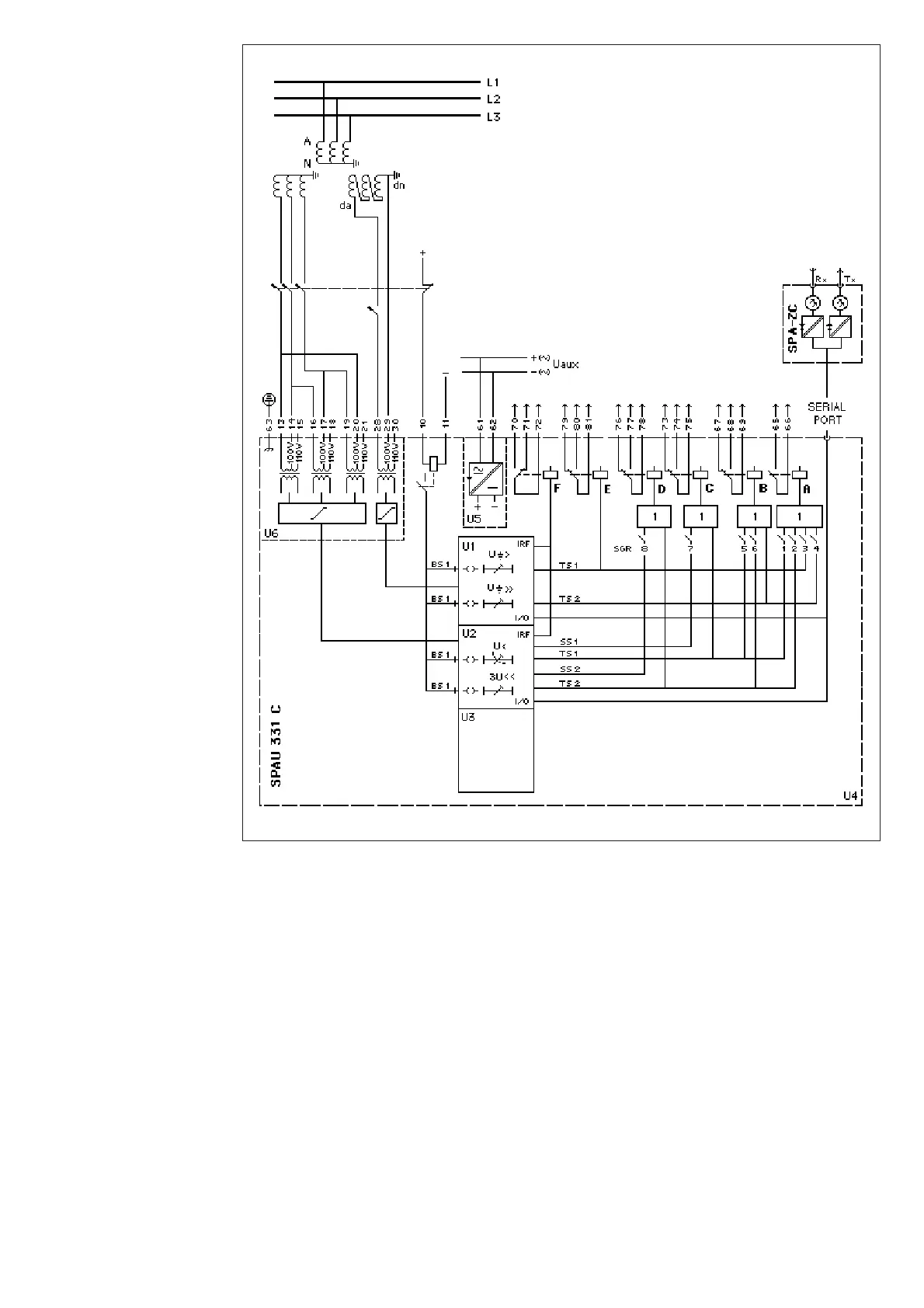
Fig. 2. Connection diagram for the voltage relay SPAU 331 C.
U
aux
Auxiliary supply voltage
A, B…F Output relays
IRF Self-supervision alarm
SGR Switchgroup for programming of starting and tripping signals
U1 Residual overvoltage relay module SPCU 1 C6
U2 Undervoltage relay module SPCU 3C15
U3 Unoccupied module place
U4 Output relay module SPTR 6B3
U5 Power supply module SPGU 240A1 or SPGU 48B2
U6 Energizing input module SPTE 4B9
SPA-ZC_ Bus connection module
Rx/Tx Optical fibre receiver (Rx) and transmitter (Tx) of the bus connection module
 Loading...


