9
Signal flow
diagram and
configuration
switches
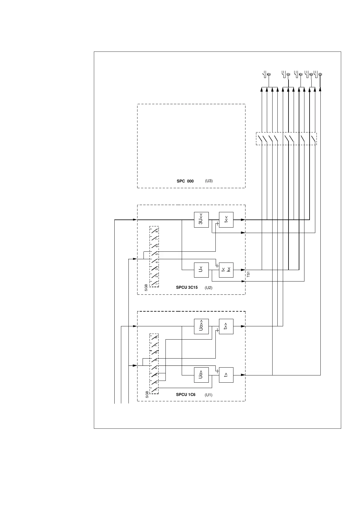
In certain applications it may be necessary to
alter the factory settings of the configuration
switches of the relay SPAU 331 C. Fig. 5 illus-
trates schematically how the starting, tripping,
control and blocking signals can be routed in-
side the relay to obtain the protection functions
required by the intended application.
Fig. 5. Control signal routes between the relay modules of the voltage relay SPAU 331 C.
BS1
Uo
234 567 81
Uo>
Uo>>
t>
t>>
TS1
TS2
23456781
t<
SS1
SS2
TS1
TS2
U<
k<
3U<<
t<<
SGB
SGB
SPCU 1C6
(U1)
SPCU 3C15
(U2)
SPC 000
(U3)
SGR
1
2
3
4
5
6
7
8
B
C
D
E
A
U
12,
U
23,
U
31
 Loading...


