5
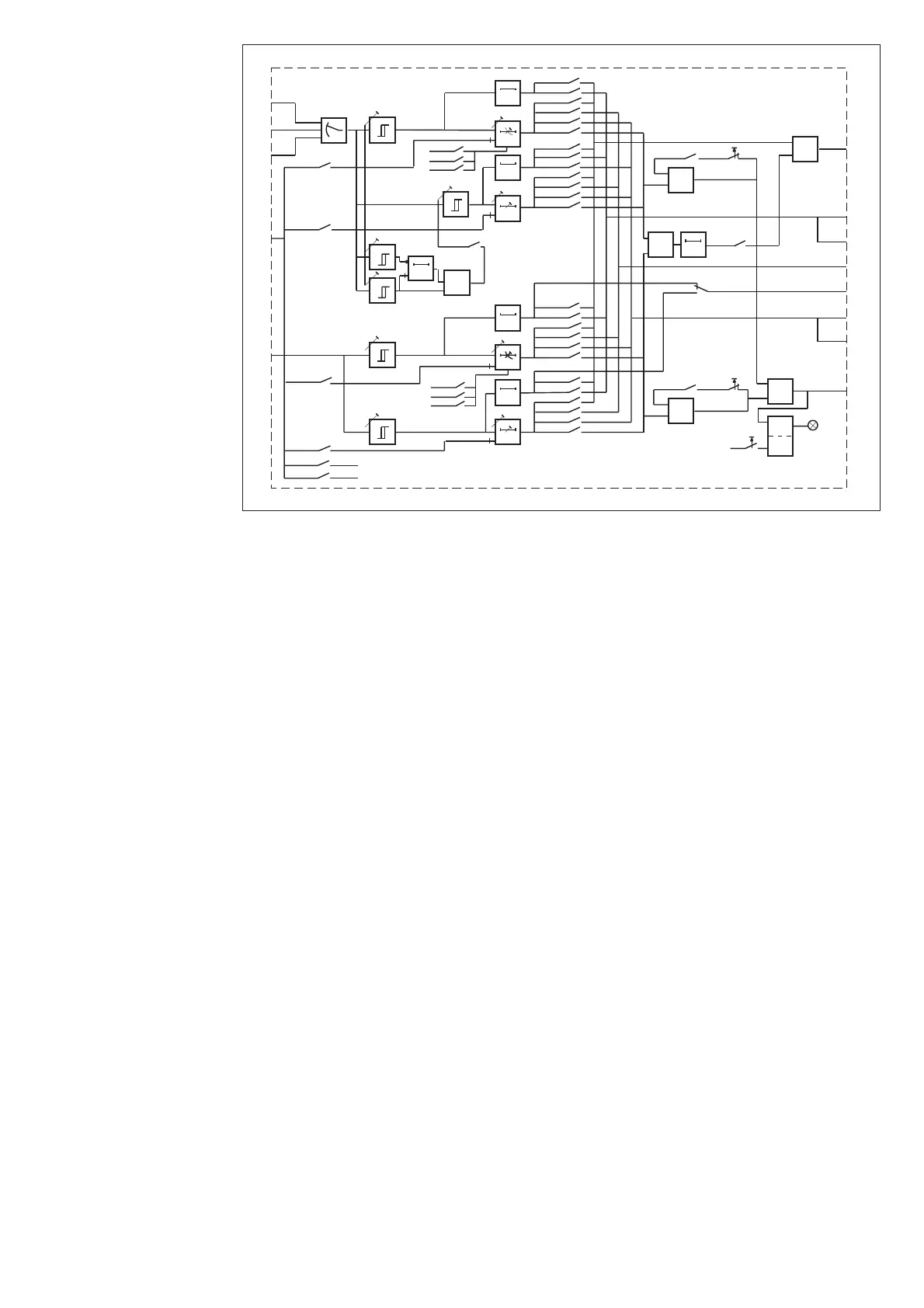
Fig. 1. Block diagram for the combined overcurrent and earth-fault relay module SPCJ 4D29.
I
L1
, I
L2
, I
L3
Energizing currents
I
0
Residual current
BS External control signal
SGF1…2 Selector switchgroup SGF for operational relay functions
SGB Selector switchgroup SGB for special relay functions
SGR1...3 Selector switchgroups SGR for configuration of output relays
TS1 Start signal 1 or auxiliary trip signal configured with switchgroup SGR3
SS1 Start signal configured with switchgroup SGR1
SS2 Trip signal 1 configured with switchgroup SGR2
SS3 Trip signal 2 configured with switchgroup SGR2
TS2 Trip signal configured with switchgroup SGR1
AR1, AR2, AR3 Start signals to possible external optional auto-reclose relays
TRIP Red operation (trip) indicator
Note!
All input and output signals of the relay module
are not necessarily wired to the terminals of a
particular relay. The signals wired to the termi-
nals of a particular protection relay are shown in
the signal diagram in the general part of the relay
manual.
Block diagram
IL1
IL2
IL3
50 ms
30 ms
50 ms
30 ms
0.12 x I>
60 ms
&
SGR3 / 1
SGR1 / 1
SGR3 / 2
SGR2 / 1
SGR2 / 2
SGR1 / 2
SGR3 / 3
SGR1 / 3
SGR3 / 4
SGR2 / 3
SGR2 / 4
SGF1 / 5
SGR1 / 4
2 x I>>
1.5 x I>
SGR3 / 5
SGR1 / 5
SGR3 / 6
SGR2 / 5
SGR2 / 6
SGR1 / 6
SGR3 / 7
SGR1 / 7
SGR3 / 8
SGR2 / 7
SGR2 / 8
SGR1 / 8
I>
I>>
t>>
t>, k
t
0
>, k
0
I
0
>
t
0
>>
I
0>>
SGF1 / 1
SGF1 / 2
SGF1 / 3
SGF1 / 6
SGF1 / 7
SGF1 / 8
Io
BS
SGB / 1
SGB / 2
SGB / 3
SGB / 4
SGB / 5
SGB / 8
REMOTE SETTINGS
RELAY RESET
1
SGB / 6
RESET+
1
SGB / 7
RESET+
1
1
1
SGF1 / 4
SS1
SS2
SPCJ 4 D 29
TS2
SS3
TRIP
0.1…1s
SGF2 / 7
AR2
AR1
AR3
SGF2 / 8