7
Control signals
between the
modules
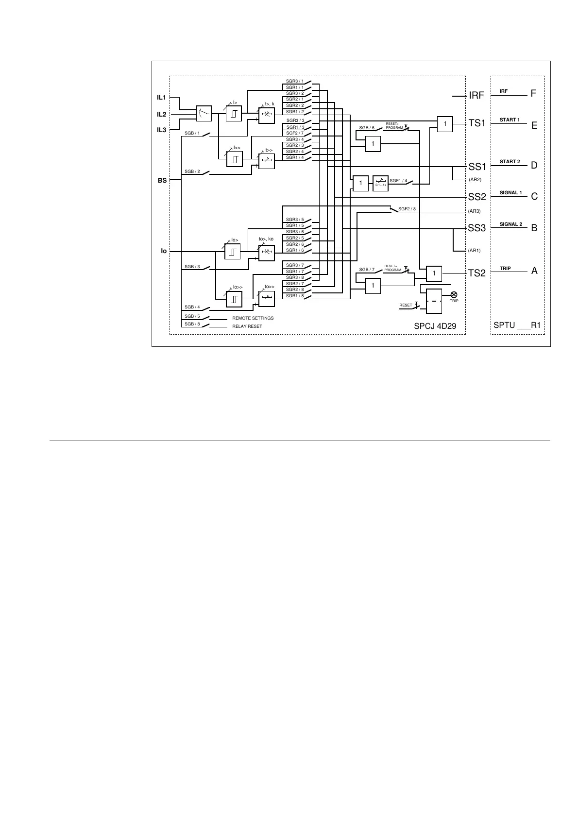
The figure below schematically illustrates how
the starting, tripping, control and blocking sig-
nals can be programmed to obtain the required
function of the protection.
Fig. 4. Control signals between the modules of the overcurrent and earth-fault relay SPAJ 142 C.
The functions of the blocking and starting sig-
nals are selected with the switches of switch-
groups SGF, SGB and SGR. The checksums of
the switchgroups, are found in the setting menu
of the measuring relay module. The functions
of the different switches are explained in the
user´s manual of the measuring module SPCJ
4D29.
Signal
abbreviations
used
I
L1
, I
L2
, I
L3
Phase currents to be measured
I
0
Neutral current
BS Blocking or control Signal
SS1 Starting Signal 1
SS2 Starting Signal 2
SS3 Starting Signal 3
TS1 Tripping Signal 1
TS2 Tripping Signal 2
BS Blocking Signal
AR1...3 Auto-Reclose starting signals (not in use in SPAJ 142 C)
IRF Internal Relay Fault signal
SGF Switch Group for Functions
SGB Switch Group for Blockings
SGR Switch Group for Relay configuration
IRF Internal Relay Fault
Rx/Tx Receiver/Transmitter channel
SGR3 / 6
SGR1 / 8
IL1
IL2
IL3
SGR3 / 1
SGR1 / 1
SGR3 / 2
SGR2 / 1
SGR2 / 2
SGR1 / 2
SGR3 / 3
SGR1 / 3
SGR3 / 4
SGR2 / 3
SGR2 / 4
SGR1 / 4
SGR3 / 5
SGR1 / 5
SGR2 / 5
SGR2 / 6
SGR1 / 6
SGR3 / 7
SGR1 / 7
SGR3 / 8
SGR2 / 7
SGR2 / 8
I>
I>>
t>>
t>, k
to>, ko
Io>
to>>
Io>>
Io
BS
SGB / 1
SGB / 2
SGB / 3
SGB / 4
SGB / 5
SGB / 8
REMOTE SETTINGS
RELAY RESET
1
SGB / 6
RESET+
PROGRAM
1
SGB / 7
RESET+
PROGRAM
1
1
1
SGF1 / 4
SS1
SS2
SPCJ 4D29
TS1
TS2
SS3
RESET
TRIP
0.1...1s
A
B
C
D
F
IRF
E
START 1
START 2
SIGNAL 1
SIGNAL 2
TRIP
IRF
(AR2)
(AR1)
(AR3)
SGF2 / 8
SGF2 / 7
SPTU ___R1
 Loading...