
S
Susan MartinJul 26, 2025
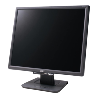
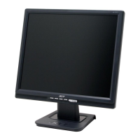
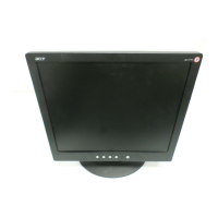
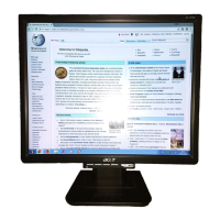
What to do if there is no picture on Acer Monitor?
- VValerie JacksonJul 26, 2025
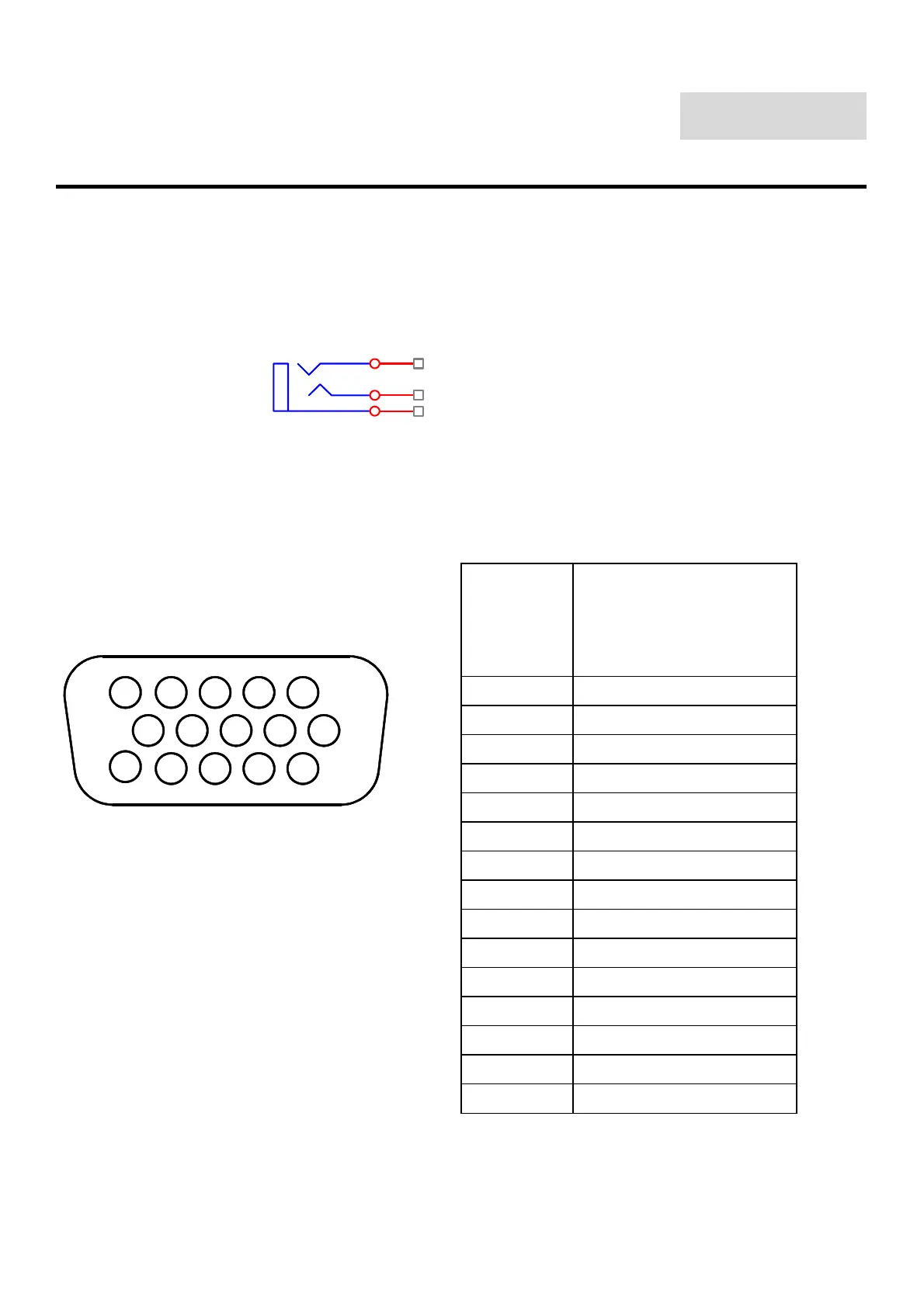
If there is no picture on your Acer Monitor, ensure that the power switch is in the ON position and the power cord is connected securely. Also, verify that the video cable is securely connected to both the monitor and the computer. Finally, try moving the mouse or pressing any key on the keyboard to bring the monitor out of "active off" mode.