EasyManua.ls Logo

Acer PREDATOR G5900 User Manual

Acer PREDATOR G5900
104 pages
To Next Page IconTo Next Page
To Previous Page IconTo Previous Page
Page #76 background imageLoading...
Page #76 background image
Chapter 5 68
Jumper Setting
The section explains how to set jumper for correct configuration of the mainboard.
Setting Jumper
Use the motherboard jumpers to set system configuration options. Jumpers with more Than one pin are
numbered. When setting the jumpers, ensure that the jumper caps are Placed on the correct pins.
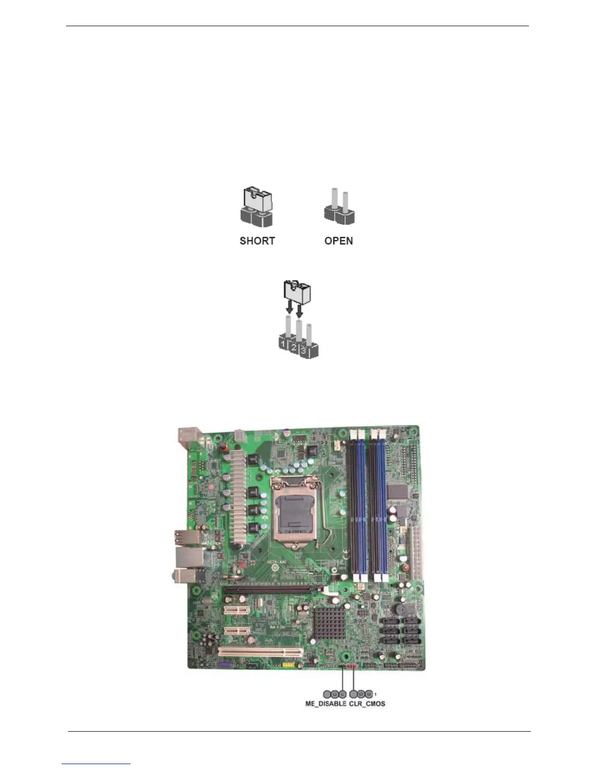
The illustrations show a 2-pin jumper.When the jumper cap is placed on bothpins, the jumper is SHORT. If you
re-move the jumper cap, or place the jumpercap on just one pin, the jumper is OPEN.
This illustration shows a 3-pin jumper.Pins 1 and 2 are SHORT.
Checking Jumper Settings
The following illustration shows the location of the motherboard jumpers. Pin 1 islabeled.

Table of Contents

Questions and Answers:

Acer PREDATOR G5900 Specifications

General IconGeneral
Operating SystemWindows 7 Home Premium
NetworkingGigabit Ethernet
ModelPREDATOR G5900
Graphics CardNVIDIA GeForce
Optical DriveDVD Super Multi
AudioHigh-definition audio support
PortsUSB 2.0

Summary

Revision History

Copyright

Disclaimer

Conventions

Service Guide Coverage

FRU (Field Replaceable Unit) List

Inter RIAD SOP

Procedure for checking Intel Matrix Storage Technology in DOS environment.

System Tour

Features

Provides a brief summary of the computer's features for reference.

Block Diagram

Illustrates the system's internal architecture and component connections.

System Components

Identifies and describes the computer's interior and exterior components.

Hardware Specifications and Configurations

Details the system's hardware specifications and configurations.

Power Management Function(ACPI support function)

Explains the ACPI power management functions and modes.

System Utilities

CMOS Setup Utility

Explains the hardware configuration program built into the system ROM.

Entering CMOS setup

Provides step-by-step instructions on how to enter the CMOS setup utility.

Navigating Through the Setup Utility

Details the keys used to navigate and interact within the BIOS setup utility.

Setup Utility Menus

Describes the main categories and parameters within the BIOS setup utility.

Product Information

Displays basic system information that is not user-configurable.

Standard CMOS Features

Covers standard CMOS settings like system date, time, and SATA port configuration.

Advanced BIOS Feature

Details advanced BIOS settings for boot order, boot behavior, and USB beep messages.

Advanced Chipset Features

Explains advanced chipset features like EIST, Turbo Boost, and Virtualization Technology.

Integrated Peripherals

Allows enabling/disabling onboard peripherals like SATA, USB, Audio, and LAN controllers.

Power Management Setup

Configuration options for ACPI suspend modes, wake-up events, and power loss behavior.

PC Health Status

Monitors system temperature, voltage, fan speed, and controls smart fan functionality.

Frequency/Voltage Control

Allows adjustment of system clocks, spread spectrum, and turbo mode settings.

BIOS Security Features

Provides options for setting and managing passwords for BIOS access.

Load Default Settings

Allows loading default BIOS settings, with a warning about potential performance impact.

Save & Exit Setup

Saves the configured changes and exits the BIOS setup utility.

Exit Without Saving

Discards any changes made and exits the BIOS setup utility.

System Disassembly

Disassembly Requirements

Lists the tools required for disassembling the computer and notes on screw management.

Pre-disassembly Procedure

Outlines the essential steps to take before starting any disassembly process.

Removing the Side Panel

Step-by-step guide on how to remove the computer's side panel.

Removing the Front Bezel

Instructions for removing the front bezel of the computer chassis.

Removing the Heat Sink Fan Assembly

Procedure for safely disconnecting and removing the heat sink fan assembly.

Removing the Processor

Detailed steps for safely removing the CPU from the motherboard socket.

Removing the VGA Card

Instructions on how to remove the VGA card from its slot.

Removing the Wireless LAN Card

Procedure for removing the wireless LAN card from the motherboard.

Removing the Memory Modules

Step-by-step guide on how to remove RAM modules from the motherboard slots.

Removing the System Fan

Instructions for disconnecting and removing the system fan.

Removing the Daughter Board

Procedure for disconnecting and removing the daughter board.

Removing Other Side Panel

Instructions for removing the opposite side panel of the computer chassis.

Removing the Hard Disk Drive

Detailed steps for disconnecting and removing the internal hard disk drive.

Removing the Removable Hard Disk Drive

Procedure for disconnecting and removing the hot-swappable HDD module.

Removing the Optical Drive

Instructions for disconnecting and removing the optical drive (CD/DVD/Blu-ray).

Removing the Power Supply

Step-by-step guide on how to disconnect and remove the power supply unit.

Removing the Motherboard

Procedure for disconnecting cables and removing the motherboard from the chassis.

Removing the Card Reader

Instructions for removing the internal card reader assembly.

Removing the Top Cover

Procedure for disconnecting cables and removing the computer's top cover.

Removing the Power Switch and LED Cable Assembly

Guide to removing the power switch and LED indicator cable assembly.

Removing the Front I/O and USB Board

Instructions for removing the front panel I/O and USB board.

System Troubleshooting

Hardware Diagnostic Procedure

Instructions for performing diagnostic tests on Acer products for troubleshooting.

System Check Procedures

Steps for performing power system checks and external/internal system inspections.

Power System Check

Checks to perform if the system does not power on.

System External Inspection

External checks to perform to identify potential malfunctions.

System Internal Inspection

Detailed steps for internal inspection of components after system disassembly.

Beep Codes

Explanation of beep codes generated by the BIOS to indicate errors.

Checkpoints

Information about BIOS checkpoints and their meaning during the boot process.

Bootblock Initialization Code Checkpoints

Details checkpoints related to the bootblock initialization code.

Bootblock Recovery Code Checkpoints

Lists checkpoints related to the bootblock recovery process.

BIOS Recovery

Procedure for performing BIOS recovery if the system's bootblock is healthy.

Jumper and Connector Information

M/B Placement

Diagram showing the placement of motherboard components.

Jumper and Connector Information

Details specific jumpers and connectors on the motherboard.

Jumper Setting

Explains how to set motherboard jumpers for system configuration options.

Checking Jumper Settings

Illustrates the location of motherboard jumpers and pin labeling.

Jumper Settings

Table detailing specific jumper types, descriptions, and their default settings.

Connecting Optional Devices

Information on connecting optional devices to the motherboard's headers.

SATA1~6: Serial ATA connectors

Details the SATA connectors for high-speed data transfer.

F_AUDIO1: Front Panel Audio header for Azalia

Explains the front panel audio header for microphone and line-out ports.

F_USB1~4: Front Panel USB headers

Details front panel USB headers for connecting case USB ports to the motherboard.

SPDIF_OUT1: SPDIF out header

Describes the optional SPDIF out header for digital multimedia output.

SPI_DEBUG: SPI_DEBUG header

Information about the SPI debug header.

GPIO0~1: Button recovery jumper

Details the GPIO pins for button recovery jumper functionality.

Connecting Case Components

Instructions for connecting motherboard components to the case.

CPU_FAN1: CPU Cooling FAN Power Connector

Details the CPU fan connector and its pinout.

ATX_POWER: ATX 24-pin Power Connector

Pinout details for the ATX 24-pin power connector.

SYS_FAN1: System Cooling FAN Power Connector

Details the system fan connector and its pinout.

ATX12V1: ATX 12V Power Connector

Pinout details for the ATX 12V power connector.

Front Panel Header

Provides information on the front panel header for switches and LEDs.

FRU (Field Replaceable Unit) List

NOTES

Important notes regarding ordering FRU parts, disposal, and updates.

Predator G5900 Exploded Diagram

An exploded view diagram of the Predator G5900 showing component identification.

Intel RAID SOP

1.INTEL® MATRIX STORAGE TECHNOLOGY CHECK(DOS)

Procedure for checking Intel Matrix Storage Technology in DOS environment.

1-1: Create SATA RAID 0

Steps to create a SATA RAID 0 volume using Intel Matrix Storage Manager.

1-2: Create SATA RAID 1

Steps to create a SATA RAID 1 volume using Intel Matrix Storage Manager.

1-3: Create SATA RAID 5

Steps to create a SATA RAID 5 volume using Intel Matrix Storage Manager.

1-4: Create SATA RAID 0+1

Steps to create a SATA RAID 0+1 volume using Intel Matrix Storage Manager.

2.Intel(R) Matrix Storage Console

Guide to using the Intel Matrix Storage Console for RAID management.

Related product manuals