73 Chapter 5
SYS_FAN1: System Cooling FAN Power Connector
ATX12V1: ATX 12V Power Connector
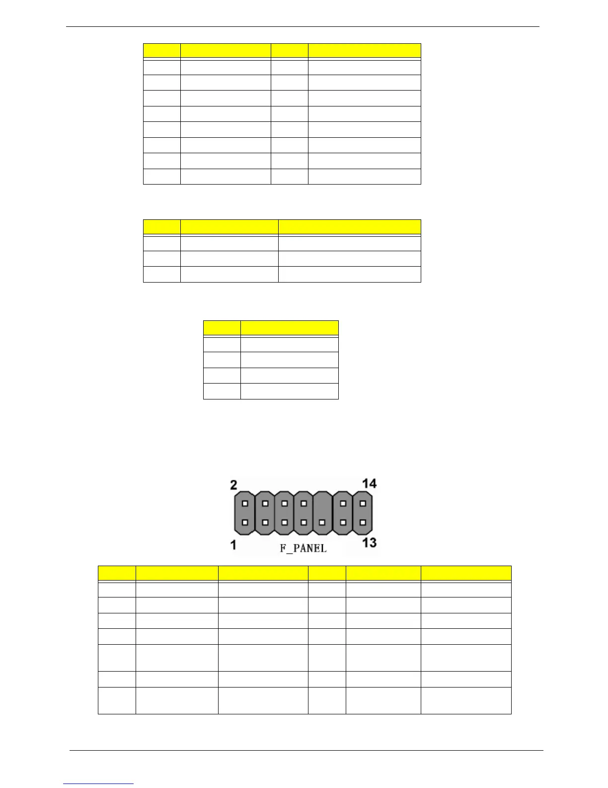
Front Panel Header
The front panel header (F_PANEL) provides a standard set of switch and LEDheaders commonly found on
ATX or micro-ATX cases. Refer to the table below forinformation:
5 Ground 17 Ground
6 +5V 18 Ground
7 Ground 19 Ground
8PWRGD 20-5V
9+5VSB 21+5V
10 +12V 22 +5V
11 +12V 23 +5V
12 +3.3V 24 Ground
Pin Signal Name Function
1 GND System Ground
2 +12V Power +12V
3 Sense Sensor
Pin Signal Name
1 Ground
2 Ground
3+12V
4+12V
Pin Signal Name Function Pin Signal Name Function
1 VCC 5V 2 GLED0 MSG LED
3 HDD_LEDN Hard disk LED 4 GLED1 MSG LED
5 GND Ground 6 PWRSW Power Switch
7 HWRST_L Reset 8 GND GROUND
9 F_PANEL_DET FRONT PANEL
DETECT
10 KEY No pin
11 NC Reserved 12 VCC 5V
13 NC Reserved 14 F_LAN_LED FRONT PANEL
LED
Pin Signal Name Pin Signal Name
 Loading...