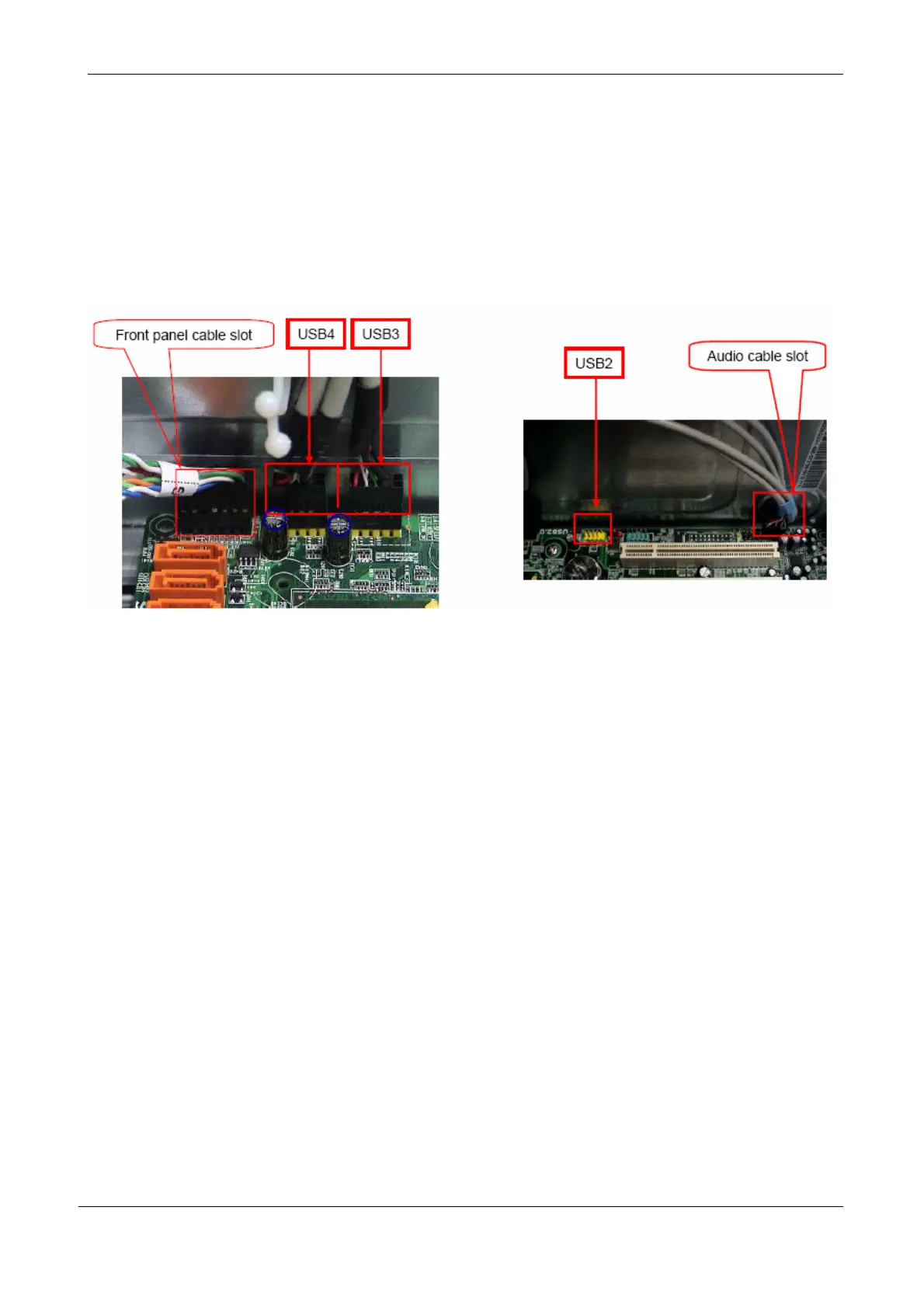
EasyManuals Logo

Acer Veriton M265 User Manual

Acer Veriton M265
109 pages
To Next Page IconTo Next Page
To Previous Page IconTo Previous Page
Page #51 background image
45
Remove Cables
Process:
1. Remove front panel light cable from“PANEL1” slot of M/B.
2. Remove USB1 cable from M/B”F_ USB3”
3. Remove USB2 cable from M/B”F_ USB4”
4. Remove Card reader cable from M/B”USB2”.
5. Remove audio cable from the “AUDIO” port on M/B.
Notice:
I. Recovery switch cable is next to FDD port, and the black cable face to the top of
Chassis.
II. Intrusion switches cable face to front bezel of chassis.
Remove HDD
Process:
1. Remove Master HDD from the first HDD location.
2. Remove Slave HDD from the second HDD location. (Optional by SKU)

Other manuals for Acer Veriton M265

Questions and Answers:

Question and Answer IconNeed help?

Do you have a question about the Acer Veriton M265 and is the answer not in the manual?

Acer Veriton M265 Specifications

General IconGeneral
Processor model-
Processor familyIntel® Core™2 Duo
Processor frequency2.4 GHz
Processor manufacturerIntel
Number of processors installed1
Internal memory2 GB
Internal memory typeDDR2-SDRAM
Maximum internal memory4 GB
Memory layout (slots x size)- GB
HDD interfaceSATA
Optical drive typeDVD-RW
Card reader integratedNo
Total storage capacity320 GB
Intel segment taggingEnterprise, Small Business
On-board graphics cardYes
Discrete graphics card modelIntel® GMA 3100
Operating system installedFreeDOS
Compatible operating systemsWindows XP/7 FreeDOS
PS/2 ports quantity2
USB 2.0 ports quantity6
Firewire (IEEE 1394) ports0
Chassis typeTower
Product colorBlack
Product typePC
Weight and Dimensions IconWeight and Dimensions
Depth440 mm
Width180 mm
Height352 mm

Related product manuals