b) Tuning Procedure
(1) Once the antenna and band have been selected (and the TUNE and LOAD adjustments
have been initially set as indicated in Table 4-1 Approximate tuning preset), apply between
10 and 20 W of continuous (key down CW) drive signal.
(2) Look at the upper LED bar-graph (FORWARD POWER) and adjust the TUNE (right hand)
capacitor for maximum FWD indication.
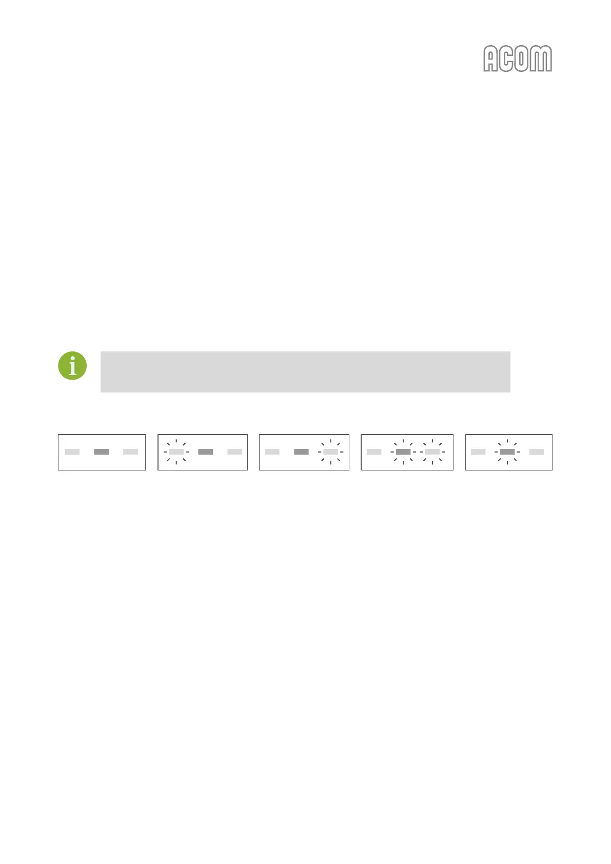
(3) Watch the three TRI LED indicators above the LOAD (left hand) knob and turn it in the
indicated direction to center the green light.
(4) Increase the drive power to get the desired nominal output; then repeat steps (2) and
(3), always peaking output with the TUNE adjustment.
No light on the TRI indicator means that the tuning is too far off. To correct this, turn the
LOAD and TUNE knobs around the table-suggested positions until the TRI indicator
illuminates.
Figure 4-1 Using TRI tuning aid
Figure 4-1 Using TRI tuning aid
The TRI indicator will not illuminate until at least 20 W of forward power (output) is achieved. In the event
successful matching cannot be accomplished, check the BAND switch position and antenna selection. Then
check the antenna SWR at the same drive frequency.
c) Tuning hint
A benefit of TRI is that the knob positions are virtually independent. The plate-load resistance decreases to
the right and increases to the left of the TRI center. A centered tuning indication corresponds to the proper
LOAD capacitor tuning, which presents an optimum load resistance to the tube.
If the LOAD knob is turned to the left with a centered TRI, there will be more gain, but less linearity. When
available drive power is insufficient or when less output but better efficiency is needed, e.g., for RTTY and
SSTV, this may be desirable. Tuning to the right of the center would lead to the opposite result, i.e., less
gain and more power attainable. Of course, this requires more drive power, more plate current, and more
plate heat, which shortens tube's-expected life.
 Loading...


