INSTALLATION
2-2
2.3 INSTALLATION
The unit must be installed with the prescribed
clearances for service as shown in Fig 2.1 These
are the
minimum
clearance dimensions required
by AERCO. Local building codes may require
more clearance and take precedence.
KEEP UNIT AREA CLEAR AND FREE
FROM COMBUSTIBLE MATERIALS AND
FLAMMABLE VAPORS AND LIQUIDS.
WARNING !
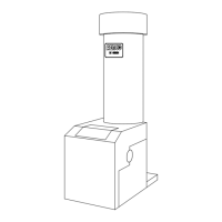
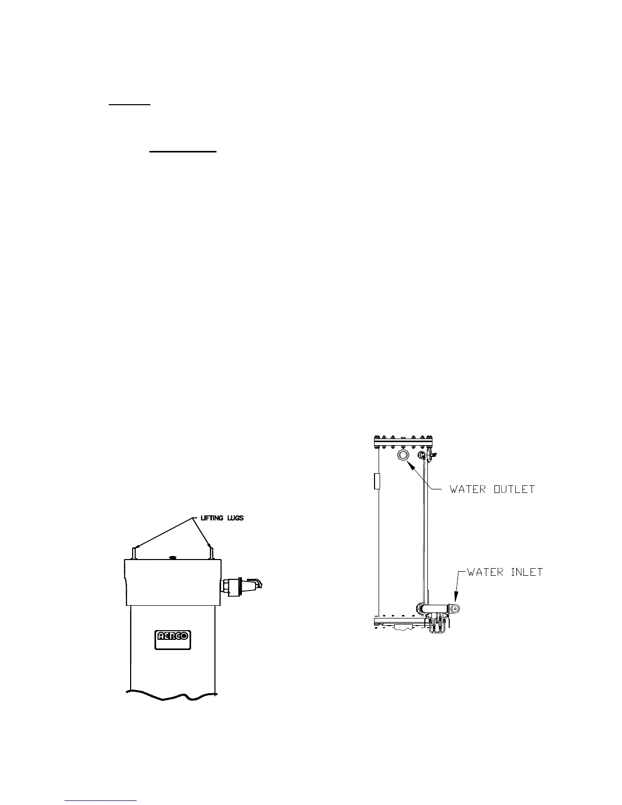
2.3.1 SETTING THE UNIT
Locate the lifting lugs, shipped with the unit, and
attach them to the 5/8” x 11 studs at the top of
the unit. Remove the unit from the wooden skid
and place in position using a block and tackle or
hoist attached to the lifting lugs. (see Fig. 2.2).
USE THE LIFTING LUGS TO MOVE THE
UNIT.
The KC-1000 is U/L approved for installation on
combustible flooring. A 4” to 6" high housekeep-
ing concrete pad is recommended and allows for
sufficient drainage of the condensate.
The unit must be secured using only the holes
provided in the frame base. Do not use piping to
secure the unit in place. See drawing AP-A-576
in Appendix E for the base frame dimensions.
In multiple unit installations, it is important to plan
the position of each unit. Sufficient space for
piping connections and maintenance require-
ments must be given. All piping must include
ample provision for expansion.
Figure 2.2
Lifting Lug Location
2.3.2 WATER INLET AND OUTLET
PIPING
The locations of the 2" NPT cold water inlet and
hot water outlet piping connections are shown in
Figure 2.3. Flow rates through the unit are
limited to 30 gpm continuous and 40 gpm
intermittent.
Shut-off valves and union conections must be
installed in the inlet and outlet lines for
maintenance. The use of dielectric unions is
recommended. Install the piping and accesso-
ries as per the following drawings, located in
Appendix F of this manual.
• SD-A-424 for single units
• SD-A-425 for multiple units
• SD-A-432 for single units with a stratified
tank
• SD-A-434 for multiple units with a stratified
storage tank
NOTE:
All piping must be arranged so that it does
not interfere with removal of any cover,
inhibit service or maintenance, or prevent
access between the unit and walls, or
another unit.
Figure 2.3
Inlet and Outlet Location
 Loading...