Do you have a question about the AERMEC FCLI 42 and is the answer not in the manual?
Advice on manual storage, careful reading, and contacting service for irregularities.
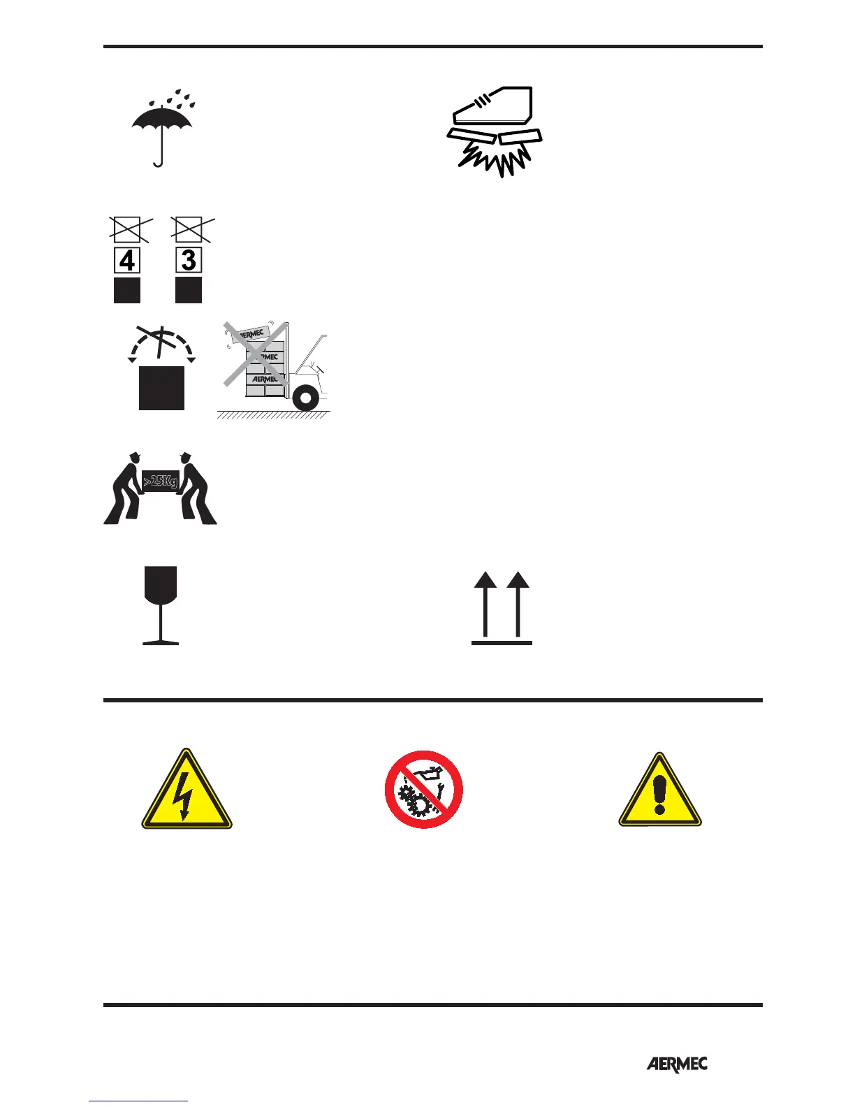
Symbols for safe handling, stacking, and weight limits for transport.
Instructions for handling the unit with care due to its fragile nature.
Symbols indicating hazards such as danger, tension, moving parts, and rotating parts.
Warnings about electrical wirings and installation by qualified technicians.
Precautions for safe operation, including disconnecting power, proper PPE, and prohibited uses.
Advice on air jet direction, water temperature, filter cleaning, and normal operating noises.
Instructions for handling malfunctions, including power cycling and contacting service.
Overview of FCLI cassette-type fan coils for suspended ceilings and room air treatment.
Details on precision temperature control, noise comfort, and energy savings from brushless motor.
List of available FCLI fan coil sizes for 2-pipe and 4-pipe systems.
Description of the obligatory GLLI accessory for intake and delivery grille.
Information on the need for an external control panel with thermostat and speed control.
Details on standard, VL, and V2 versions of the fan coil, differing by valve configuration.
Numbered list and diagrams identifying main components of FCLI units.
Detailed descriptions of the unit's base, brackets, tray, coil, valve, fan, and motor.
Diagrams illustrating hydraulic and electrical connections for 2-pipe systems.
Diagrams illustrating hydraulic and electrical connections for 4-pipe systems.
Diagrams for FCLI VL units, showing connections for systems without valves.
Summary of main technical data for FCLI range in tables and diagrams.
Table detailing maximum operating temperatures, pressure, humidity, and power supply.
Advice on water temperature to prevent air stratification and squeaking.
Table showing minimum water temperatures to avoid external condensate formation.
Tables showing heating output and pressure drop data for FCLI 2-pipe models.
Tables showing cooling capacity and water flow rate for FCLI 2-pipe models.
Tables detailing sensible cooling capacity and pressure drop for FCLI 2-pipe models.
Data on air flow rate, sound power, sound pressure, and input power for fans.
Specifications for water connections, Kvs values, IP rating, and heat exchanger content.
Indicates EUROVENT certification for sound tests and performance values.
Tables showing heating output and water flow rate for FCLI 4-pipe models.
Tables detailing pressure drop and cooling capacity for FCLI 4-pipe models.
Data on sensible cooling capacity and air flow for FCLI 4-pipe models.
Tables for sound power and sound pressure levels for FCLI 4-pipe models.
Specifications for input power, current, and heat exchanger water content.
Tables showing cooling capacity (Pc) and sensible capacity (Ps) under various conditions.
Correction factors (k) for determining cooling capacity based on fan speed (air flow).
Continuation of tables showing cooling capacity (Pc) and sensible capacity (Ps).
Continuation of correction factors (k) for fan speed adjustment of cooling capacity.
Tables showing cooling capacity (Pc) and sensible capacity (Ps) for FCLI 42.
Correction factors (k) for fan speed adjustment of cooling capacity for FCLI 42.
Continuation of tables for cooling capacity (Pc) and sensible capacity (Ps) for FCLI 42.
Continuation of correction factors (k) for fan speed adjustment of cooling capacity.
Tables showing cooling capacity (Pc) and sensible capacity (Ps) for FCLI 44.
Correction factors (k) for fan speed adjustment of cooling capacity for FCLI 44.
Continuation of tables for cooling capacity (Pc) and sensible capacity (Ps) for FCLI 44.
Continuation of correction factors (k) for fan speed adjustment of cooling capacity.
Tables showing cooling capacity (Pc) and sensible capacity (Ps) for FCLI 62.
Correction factors (k) for fan speed adjustment of cooling capacity for FCLI 62.
Continuation of tables for cooling capacity (Pc) and sensible capacity (Ps) for FCLI 62.
Continuation of correction factors (k) for fan speed adjustment of cooling capacity.
Tables showing cooling capacity (Pc) and sensible capacity (Ps) for FCLI 64.
Correction factors (k) for fan speed adjustment of cooling capacity for FCLI 64.
Continuation of tables for cooling capacity (Pc) and sensible capacity (Ps) for FCLI 64.
Continuation of correction factors (k) for fan speed adjustment of cooling capacity.
Tables showing cooling capacity (Pc) and sensible capacity (Ps) for FCLI 82.
Correction factors (k) for fan speed adjustment of cooling capacity for FCLI 82.
Continuation of tables for cooling capacity (Pc) and sensible capacity (Ps) for FCLI 82.
Continuation of correction factors (k) for fan speed adjustment of cooling capacity.
Tables showing cooling capacity (Pc) and sensible capacity (Ps) for FCLI 122.
Correction factors (k) for fan speed adjustment of cooling capacity for FCLI 122.
Continuation of tables for cooling capacity (Pc) and sensible capacity (Ps) for FCLI 122.
Continuation of correction factors (k) for fan speed adjustment of cooling capacity.
Tables showing cooling capacity (Pc) and sensible capacity (Ps) for FCLI 124.
Correction factors (k) for fan speed adjustment of cooling capacity for FCLI 124.
Continuation of tables for cooling capacity (Pc) and sensible capacity (Ps) for FCLI 124.
Continuation of correction factors (k) for fan speed adjustment of cooling capacity.
Charts showing water flow rate vs. heating capacity for different temperatures.
Correction factors for adjusting heating capacity based on fan speed.
Charts showing water flow rate vs. heating capacity for different temperatures.
Correction factors for adjusting heating capacity based on fan speed.
Table showing pressure drops [kPa] for heating with 50°C water at various flow rates.
Table showing pressure drops [kPa] for heating with 70°C water at various flow rates.
Table showing pressure drops [kPa] for cooling with 7°C water at various flow rates.
Correction factors for cooling capacity, airflow, and pressure drops with glycol water.
Correction factors for heating capacity, airflow, and pressure drops with glycol water.
Tables showing sound power levels in dB(A) across frequency bands for all FCLI models.
Table showing sound pressure levels in dB(A) for different FCLI models and speeds.
Compatibility chart for selecting accessories for different FCLI models.
Details on essential accessories required for unit operation, like GLLI grilles.
Accessories for VMF system integration, including control panels and probes.
Description of the GLLI-N grille unit with VMF System thermostat and its connections.
Components of the GLLI_N accessory, including thermostat board and connection cables.
Details on thermostat control modes, inputs, and network communication capabilities.
Description of GLLI grille units, their features, and interface requirements.
Description of the FEL10 electrostatically pre-charged air filter for grille units.
Delivery flanges (KFL10, KFL20) for directing air to adjacent rooms.
Suction flanges (KFLD, KFLD20) for introducing fresh external air.
Description of motor-driven 3-way valves for heating batteries in 4-pipe systems.
Description of motor-driven 2-way valves for heating batteries in 4-pipe systems.
Wired control panel with thermostat, digital display, and speed control.
Water temperature probe for WMT20 control panels with 2m cable.
Temperature probes (SW4, VMF-SW1) for VMF System thermostats.
Wired control panel for VMF range thermostats, wall mounting.
Panel settings for device on/off, ventilation speed, and room temperature.
Diagrams illustrating TTL local networks and VMF-E5 supervisor networks.
Supervision interface for managing masters and slave units in a hydronic system.
Capabilities for managing fan coils, chillers, circulators, boilers, and heat recovery.
Warnings for power disconnection, PPE, national regulations, and qualified technicians.
Indications for positioning, air distribution, maintenance access, and prohibited locations.
Diagrams showing dimensions and installation bracket placement for modules.
Steps for choosing location, mounting the frame, and lifting the unit.
Instructions for connecting the electric box, inverter, and safety cable.
Steps for grille frame positioning, screws tightening, and functional testing.
Guidance on closing delivery outlets using gasket when installing near a wall.
Steps for choosing location, mounting the frame, and lifting the unit.
Instructions for connecting the electric box, grille frame, and safety wire.
Guidance on tightening screws, safety wire attachment, and functional testing.
Guidance on closing delivery outlets using gasket when installing near a wall.
Steps for safely disassembling the unit for maintenance, including power disconnection.
Instructions for accessing and maintaining the electric box for routine checks.
Details on water connection fittings, pipe scaling, insulation, and valve accessory.
Instructions for connecting condensate drainage, pump/float device, and overflow.
Connecting circular flanges for fresh air intake via an external fan.
Connecting circular flanges for delivering treated air to an adjacent room.
Requirements for power connection, tolerances, and fitting thermal trip protection.
Specifications for power cable types and guidance to follow wiring diagrams.
Instructions for connecting the Inverter to the electric box and warnings on parameter modification.
Connecting a control panel with thermostat and ventilation speed control.
Checking and adjusting electronic board dip-switches for system configuration.
Connecting VMF-E4 panel, network cable, TTL cable, and probes/valves.
Steps for installing and replacing the filter, including safety precautions.
Steps for installing and replacing the filter, including safety precautions.
Diagrams showing overall dimensions and connection points for FCLI 32-64 units.
Table listing the weight in kg for different FCLI models and versions.
Diagrams showing overall dimensions and connection points for FCLI 82-124 units.
Table listing the weight in kg for different FCLI 82-124 models and versions.
Table detailing alarm types, indications, irregularities, and system status.
Notes on how to reset specific alarms, including power cycle instructions.