48
IFCLITY1106 - 5773010_01
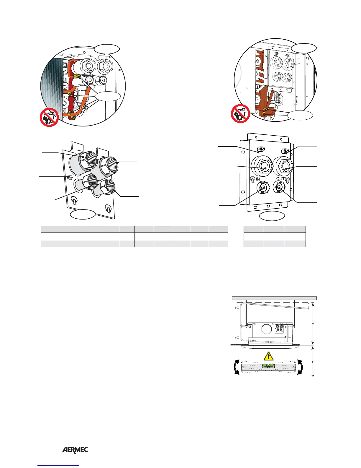
The water connections are made with flat
fittings complete with seal gaskets (supplied).
In the 4-pipe version of the unit, it is essential
to install the valve accessory for the hot water
coil; use the supplied gaskets. The accessory
comes complete with gaskets for connection
to the system.
Information for the correct installation of the
valve is contained in the accessory instruction
booklet.
The delivery and return pips must be equal,
suitably scaled and insulated to avoid heat
dispersion and dripping during cooling
operation.
The water, condensate discharge and electrical circuit ducts must be provided for.
CONNECTIONS
CONDENSATE DISCHARGE CONNECTION
During cooling operation the indoor
unit removes humidity from the air. The
condensate water must be eliminated
by connecting the appropriate discharge
coupling to the piping of the condensate
discharge system.
In units with "Module 600", the polysty-
rene tray has a hole that allows for the
complete draining of the condensate
(useful in the case of disassembly). The
drainage hole must always be closed
again with the rubber plug provided.
The units are fitted as standard with a
pump/float device for raising the
condensate from the tray to the drainage
point; it consists of an electronic card,
an electric pump with non-return valve,
and a float with a 3-level sensor (ON,
OFF and Alarm).
The power supply for the float/pump
device must never be interrupted.
In the event of an alarm, the float device
interrupts the flow of water in the coil.
The tray is fitted with an overflow hole to
ensure that the condensate water runs
off if the floating pump device is not
working. In this case dripping can be
seen from the grille.
The pump allows a maximum head of
80cm from the level of the suspended
ceiling; if this is not high enough you
will have to use an auxiliary device.
You are advised to use rigid piping that is
heat-insulated, to avoid condensation on
the outer surfaces.
SC = Condensate discharge (male Ø
16mm)
HYDRAULIC CONNECTIONS
CONNECTIONS
(2) = Standard coil connections
Air = Air vent of the standard coil
(4) = Hot water coil connections
The unit can be connected to a fresh
air suction conduit via the circular
flange accessory applied to the vent.
The application of the flange requires a
hole to be opened up on the side. The
connection with the outside is direct,
regardless of unit ventilation.
The accessory also includes a deflector,
to be assembled inside the unit.
CONNECTIONS FOR THE SUCTION OF FRESH EXTERNAL AIR
The unit can be connected to a conduit
for delivering treated air to an adjacent
room via the circular flange accessory.
The application of the flange requires a
hole to be opened up on the side.
CONNECTIONS FOR THE DELIVERY OF TREATED AIR TO AN ADJACENT ROOM
OUT
IN
(2) in
(4) out
(2) out
Air out
(4) in
600x600
(2) in
(4) out
(2) out
Air out
(4) in
Air out
840x840
OUT
600x600
Out
840x840
1/50 ~ 1/100
MAX. 800mm
MAX. 3000mm
Mod. FCLI 32 34 42 44 62 82 122 124
Standard coil connections (2)
diam. 3/4"F 3/4"F 3/4"F 3/4"F 3/4"F 3/4"F 3/4"F 3/4"F
Additional coil connections (4)
diam. 3/4"F 1/2"F 1/2"F 3/4"F 1/2"F 3/4"F 3/4"F 1/2"F
 Loading...