Do you have a question about the AERMEC WRCB and is the answer not in the manual?
| Model | WRCB |
|---|---|
| Manufacturer | AERMEC |
| Display | LCD |
| Protection Rating | IP20 |
| Operating Temperature | 0°C to +50°C |
| Type | Controller |
| Communication Protocol | Modbus |
| Humidity Range | 90% RH (non-condensing) |
Key warnings and guidelines for safe and proper use of the wired controller.
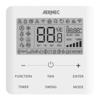
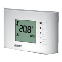
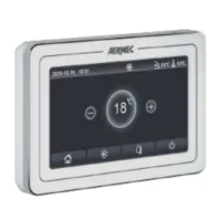
Visual identification of the wired controller's exterior and buttons.
Detailed description of all icons and indicators shown on the LCD screen.
Lists each button and its primary function and secondary uses.
Instructions for turning the unit on/off, selecting modes, and adjusting temperature.
Guide to adjusting fan speed and setting timer functions.
Detailed steps for operating the up/down and left/right swing functions.
Instructions for activating and deactivating the sleep mode.
Steps for connecting the controller to the WiFi network.
Steps for connecting the signal line between the wired controller and the indoor unit.
Guidelines for physically installing the wired controller on the wall.
Instructions on how to safely dismantle and remove the wired controller.
Procedure for assigning a serial address to the indoor unit via the CC2 interface.
Procedure for assigning a serial address to the indoor unit via the BMS connection.
A list of all possible error codes and their corresponding explanations.