Service
Chapter 3 47
Step 4. Connect the Power Sensor to channel A of the Power Meter.
NOTE Heat can affect the adjustments so handle the sensor as little as possible.
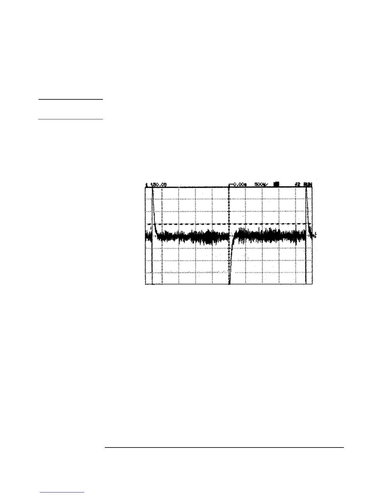
Step 5. Adjust the black/white and brown/white wires until the waveform shown on the
oscilloscope is similar to that shown in Figure 3-2. This shows an example of a High
Gain output signal with acceptable sensor offset and spike balance settings.
Figure 3-2 Example of an Acceptable Waveform
Step 6. Allow no more than 50mV variance on the sensor offset step (i.e. from top-to-top or
bottom-to-bottom of the waveform). Figure 3-3 shows an example of a High Gain
output signal with an unacceptably high sensor offset setting.

 Loading...


