Service
Chapter 350
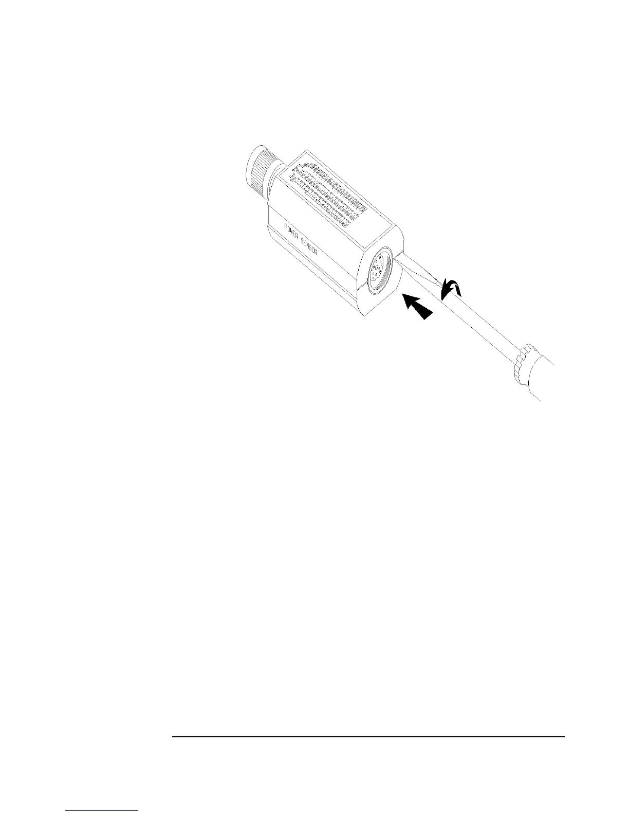
Figure 3-4 Removing the Power Sensor’s Cover
Step 2. At the other side of the sensor, again pry the cover shell sections apart. Remove the
shells and the inner magnetic shields.
Step 3. Position the Power Sensor as shown in Figure 3-5 (top). The small hole 5 should be
on the left side of the RF input connector. Remove the allen cap screws 1, 2, 10, and
13. Loosen 11 and 12. Remove the upper chassis from the Power Sensor.
Step 4. Remove the spring clamp cap screw 7 to free the gold leads which come from the
Bulkhead Assembly.
Step 5. Remove cap screws 3, 4, and 5.
Step 6. Slide the Bulkhead Assembly straight out from the chassis.
Step 7. Remove cap screws 8, 9, 11, 12, 14, and 15.
Step 8. Lift the A2 Input Amplifier and J1 connector out of the chassis.

 Loading...


