Introduction 1
Agilent 8494/95/96G/H Attenuators Operating and Service Manual 11
Table 1 on page 11, Table 2 on page 12, and Table 3 on page 12
show the typical switching arrangement to increase the amount of
attenuation in an 8494G/H, 8495G/H, or 8496G/H in a linear
manner. To ensure specified performance, it is recommended that
the attenuator sections that are shown in the following tables be
used. With the attenuator programmed for 0 dB attenuation, the
resultant attenuation is the insertion loss (residual attenuation).
The 8494G/H has a minimum selectable step of 1 dB, while the
8495G/H and 8496G/H have a minimum selectable step of 10 dB.
The accuracy of the attenuators is within the limits given in
“Specifications” on page 15.
• The 8494G/H are four- section attenuators with a maximum
attenuation of 11 dB.
• The 8495G/H are three- section attenuators with a maximum
attenuation of 70 dB.
• The 8496G/H are four- section attenuators with a maximum
attenuation of 110 dB.
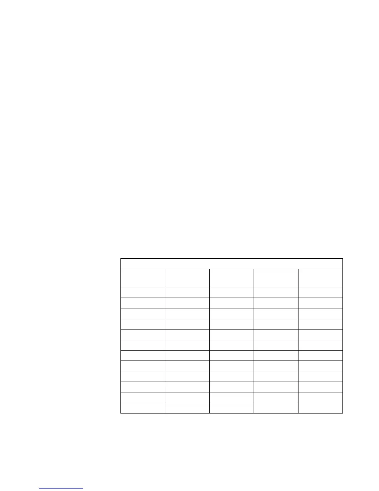
Table 1 8494G/H Attenuator Switching Order
8494G/H Attenuator Sections
Atten
(dB)
1
1 dB
2
2 dB
3
4 dB
4
4 dB
0
1 ×
2 ×
3 ××
4 ×
5 ××
6 ××
7 ×××
8 ××
9 ×××
10 ×××
11 ××××
 Loading...


