Operating Guides 3
Agilent 8494/95/96G/H Attenuators Operating and Service Manual 29
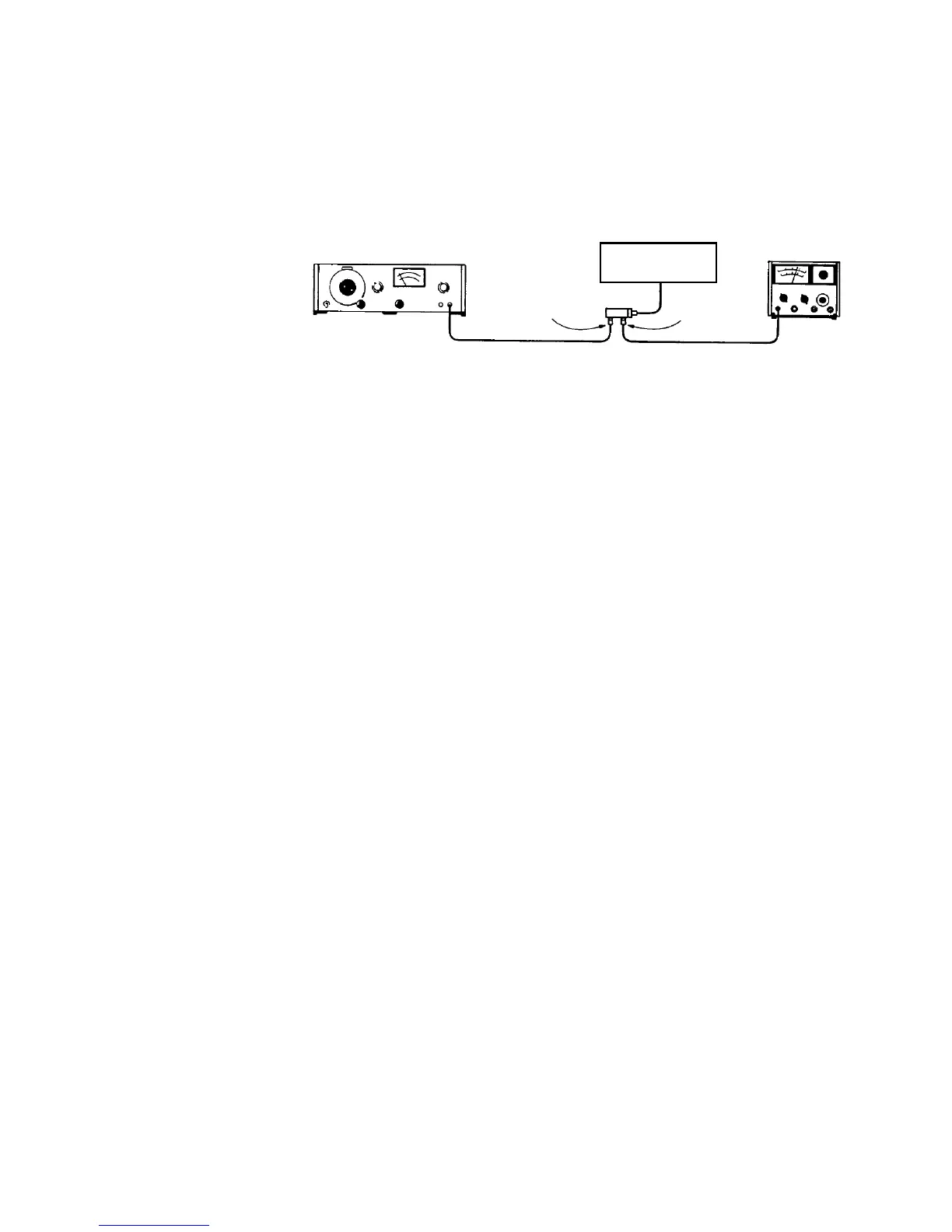
Figure 5 Operator’s Check Setup
Procedure
1 Connect equipment as shown in Figure 5 on page 29 with the
attenuator set to 0 dB attenuation.
2 Set the test oscillator to 0.3 Vrms at 1 kHz.
3 Set SWR meter range to 2 dB (expanded) [or for the 8494G/H
to 10 dB (expanded)] and adjust its bandwidth to the center of
the adjustment range. Fine- tune the oscillator frequency to
obtain maximum meter indication.
4 Set attenuator and SWR meter range switch as listed in
Table 13 and verify that the SWR meter indicates within the
limits shown.
Test oscillator
Solenoid driver
circuits
SWR meter
Attenuator
Adapter
Adapter
50 Ω
Input
 Loading...


