Introduction 1
Agilent 8494/95/96G/H Attenuators Operating and Service Manual 13
Each solenoid requires a drive of 20 V to 30 V with a switching
current of approximately 125 mA
[1]
at 24 Vdc per section. The
solenoid switching time is less than 20 milliseconds including
settling time. Once switched, the solenoid plungers are held in
place by permanent magnets and the solenoid plungers
automatically disconnect the selected coil drive and connect the
opposite coil drive (see Figure 1 and Figure 2). This simplifies the
coil driver circuit design and reduces the amount of heat
dissipated by the solenoid coils since the solenoid coils are
energized only for the 20 milliseconds switching time.
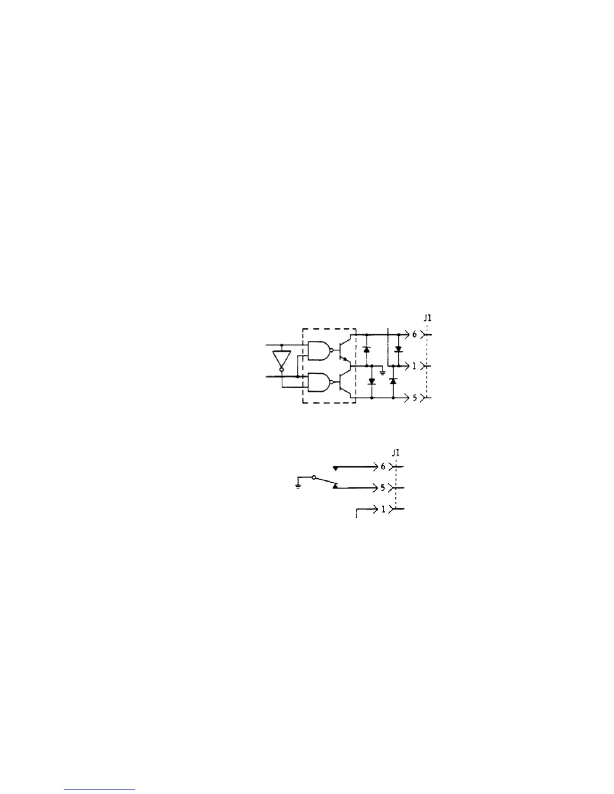
Figure 2 Typical Solenoid Coil Driver Circuits
[1] For serial number prefixes below 1722A, change 125 mA to 110 mA.
Solenoid cable
connector jack
Solenoid driver
Any 75451 dual peripheral AND driver.
+24 V
Atten card pin
Solenoid drive pin
Thru-line pin
TTL Input
1820-0175
+5 VDC
Typical Solenoid IC Driver Circuit
(3 or 4 required)
Atten card pin
Thru-line pin
Solenoid drive pin
+24 Vdc
Switch or relay
contacts
Typical Solenoid Relay or Switch Driver
(3 or 4 required)

 Loading...


