Introduction 1
Agilent 8494/95/96G/H Attenuators Operating and Service Manual 19
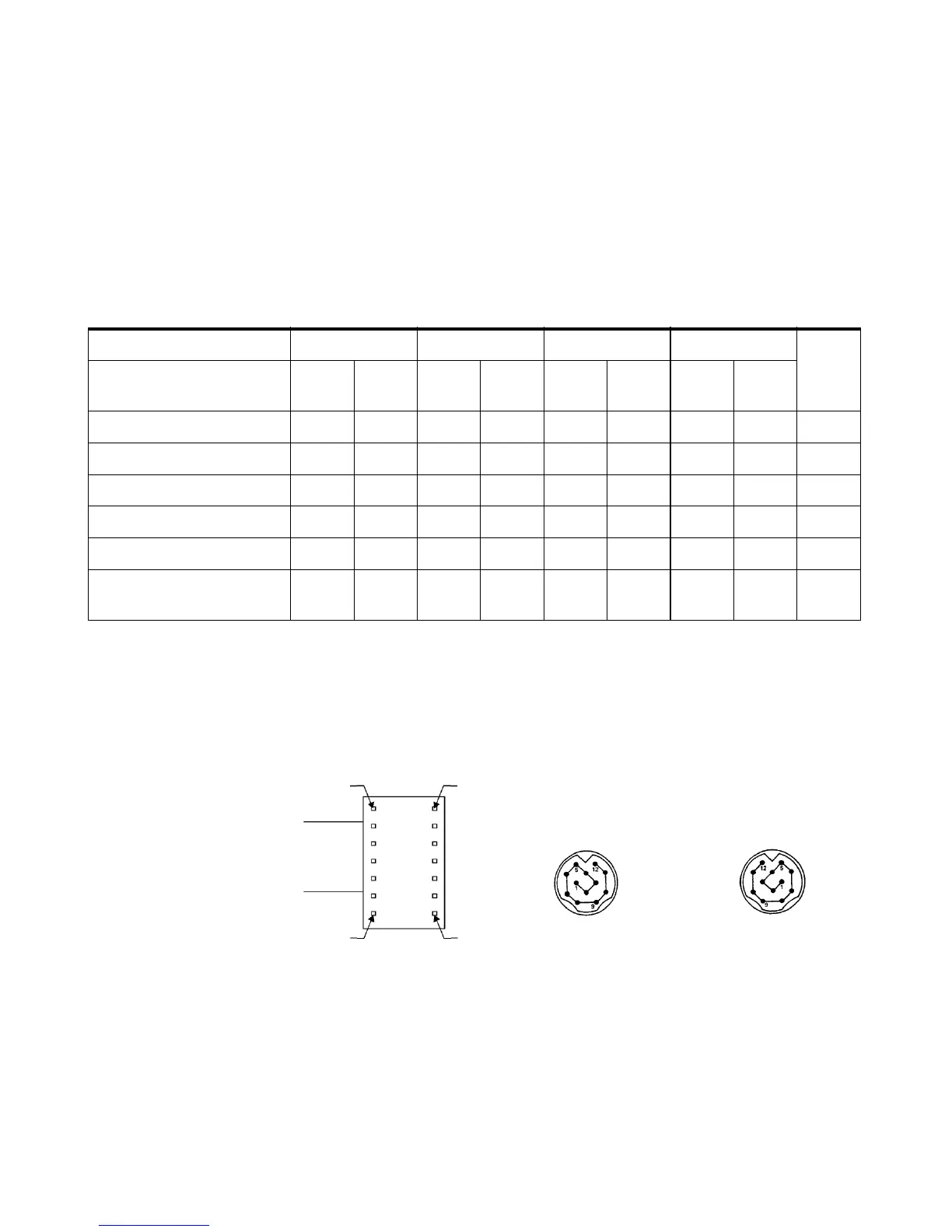
Solenoid Cable Connector
Refer also to Figure 3.
Figure 3 Solenoid Cable Pin Configuration
Table 1 0 Solenoid Cable Connector
Section Section 1 Section 2 Section 3 Section 4 Power
V+
Solenoid Coil Thru-
Line
Atten
Card
Thru-
Line
Atten
Card
Thru-
Line
Atten
Card
Thru-
Line
Atten
Card
Cable Wire Color Code
[1]
PUR YEL BLK GRN ORN BLU BRN WHT RED
Connector Plug Pin Number
[2]
567891011121
8494G/H 0 dB 1 dB 0 dB 2 dB 0 dB 4 dB 0 dB 4 dB –
8495G/H 0 dB 10 dB 0 dB 20 dB 0 dB 40 dB – – –
8496G/H 0 dB 10 dB 0 dB 20 dB 0 dB 40 dB 0 dB 40 dB –
Option 016
Flat Pack Plug Pin Number
[3]
132115 3 9 4106
[1] Five-foot cable and mating plug assembly provided.
[2] Pin 1 Common solenoid drive (+24 Vdc).
[3] Pin 6 is common for all coils. Pins 1, 7, 8, 12, and 14 are not used.
Plug, front view
Jack, front view
(1)
(7)
(8)
(14)
Plug, bottom view
Option 060
Option 016

 Loading...


