9
Scope Connection Configuration
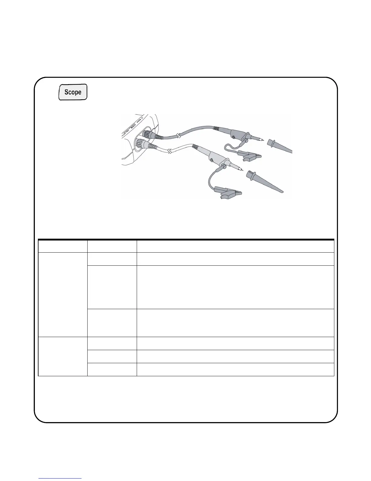
Connect the scope in either single or dual channels with scope probes as
shown in figure 3.
Figure 3 Connection for scope measurement
Scope Menu Sub Menu Description
CH1 / CH2
MORE 1/2 page
On/Off To turn on or off waveform display for channel 1 and channel 2
Coupling To select channel coupling:
DC: To display both AC and DC component of the input waveform
AC: DC offset voltage will be removed from the input waveform, only AC com-
ponent will be shown
GND: Input signal is grounded
Position To adjust the reference ground position, turn rotary switch clockwise to raise to
positive position and vice versa
To set the position, press rotary switch
CH1 / CH2
MORE 2/2 page
Probe Select the probe attenuation 1X, 10X or 100X
Invert To turn on or off waveform invert function
Position to 0 Reset the reference ground position to zero volt
Table 2
Function descriptions of scope menu
 Loading...


