11-1
TUBING CONNECTIONS
SM FLODCI 2-A.4 GB
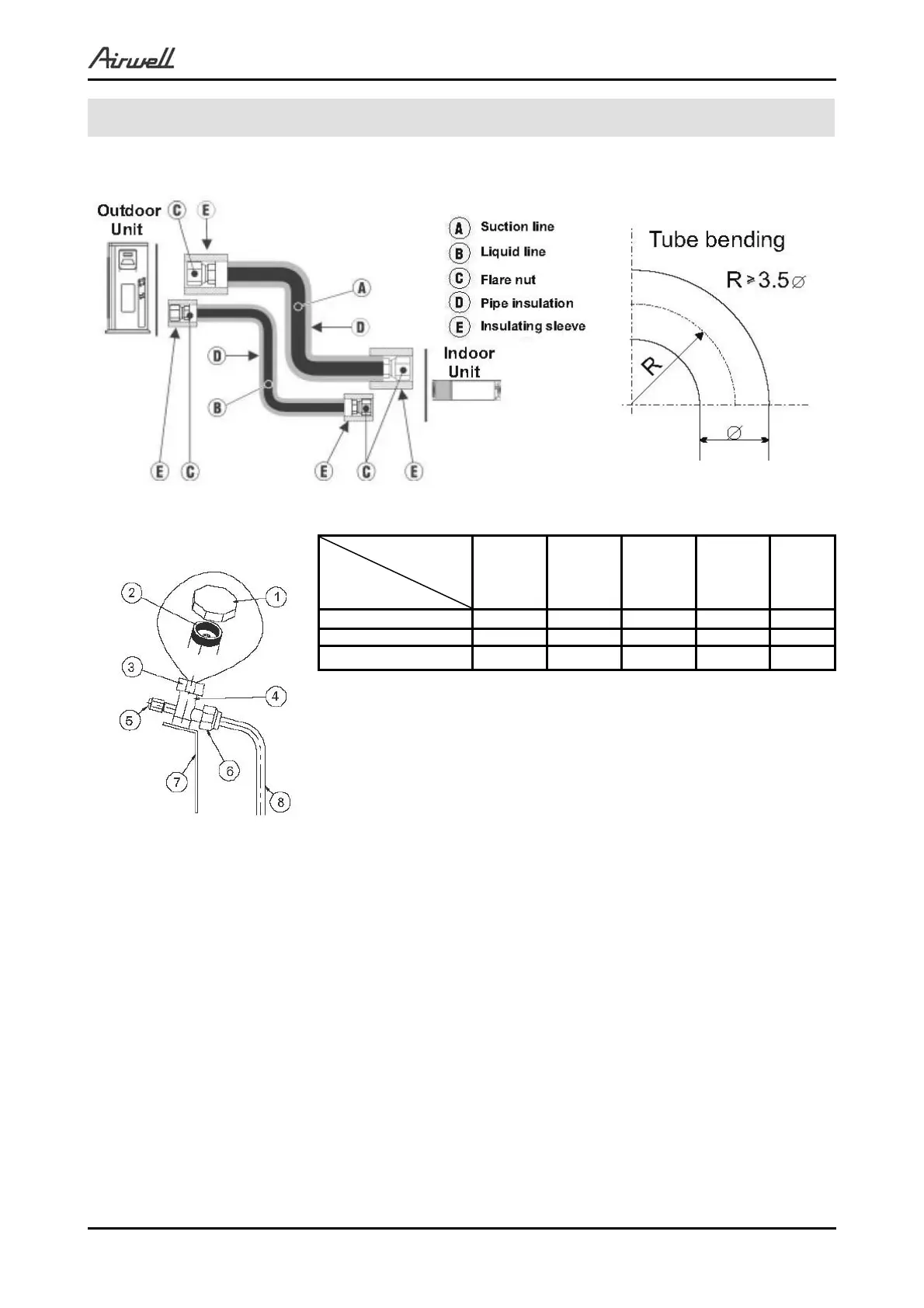
11. TUBING CONNECTIONS
TUBE (Inch)
TORQUE (Nm)
¼” ⅜” ½” ⅝” ¾”
Flare Nuts 11-13 40-45 60-65 70-75 80-85
Valve Cap 13-20 13-20 18-25 18-25 40-50
Service Port Cap 11-13 11-13 11-13 11-13 11-13
1. Valve Protection Cap-end
2. Refrigerant Valve Port (use Allen wrench to open/close)
3. Valve Protection Cap
4. Refrigerant Valve
5. Service Port Cap
6. Flare Nut
7. Unit Back Side
8. Copper Tube
When the outdoor unit is installed above the indoor unit an oil trap is required every 5m along the suction
line at the lowest point of the riser. Incase the indoor unit is installed above the outdoor, no trap is
required.
 Loading...