6
3:0 REPLACING COMPONENTS
Always switch off the 12 V DC and 230 V ~ power supply, and turn the main gas cock to the off position before
starting any servicing. The seals (marked in red) must NOT be broken unless special permission has been obtai-
ned from Alde.
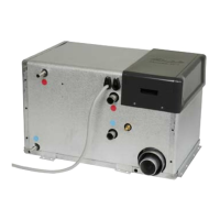
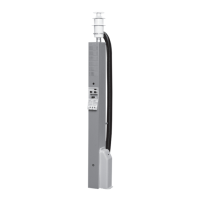
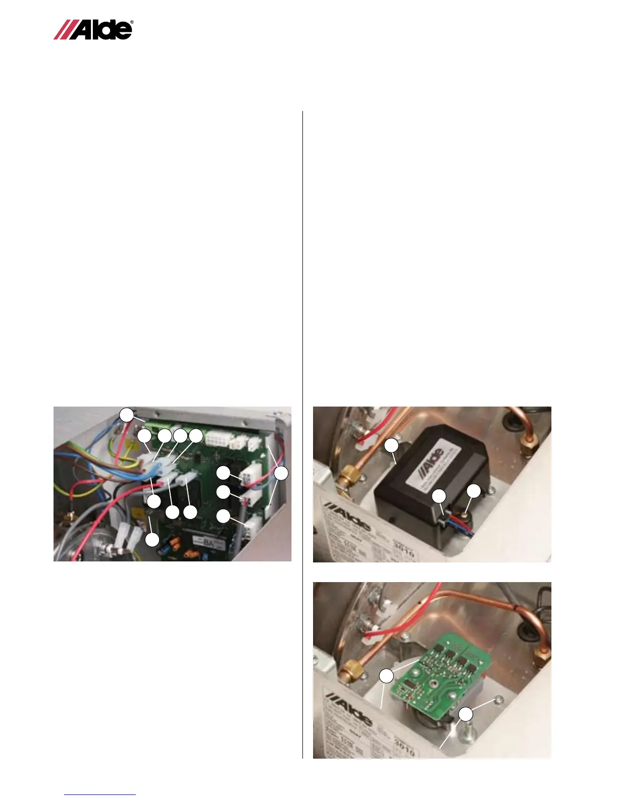
Fig 10.
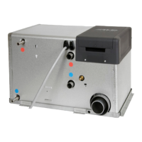
Fig 2.
A
3:1 REPLACING THE PRINTED CIRCUIT
BOARD
1. Remove the service panel on the boiler.
2. Detach the blue cable (marked Blue)(g.1A) and brown cable
(marked Brown)(g.1B), red cable (marked Red)(g. 1C),
grey cable (marked Grey)(g. 1D) and black cable (marked
Black)(g. 1E) on the printed circuit board, and the blue
(marked PUMP-N) (g.1F) and brown (marked PUMP-L)(g.
1G) if the boiler is equipped with a 230V circulation pump.
3. Release the white 6-point connection block (g.1H) from the
sensors on the printed circuit board.
4. Detach the white 4-point connection block (g.1I) from the
fan on the printed circuit board.
5. Detach the white 5-point connection block (g.1J) from the
solenoid valve on the printed circuit board.
6. Untight the hex-screw on the printed circuit board (g. 1K).
7. Remove the printed circuit board by pressing together the
three hooks, (g. 1L), and pulling out the circuit board.
8. Push the new circuit board rmly in and connect the cables
as shown in g. 1.
9. NB! Tighten the hex-screw holding the printed circuit board
(g 1K).
10.Ret the service panel and test-run the electrical heating
cartridge.
NB! Caution! Take preventative measures against static
electricity when handling the printed circuit board.
Static can damage the PCB.
3:2 REPLACING FAN
1. Remove the service panel on the boiler
2. Release the cable from the fan motor by lifting the hook
(g. 2A) and pulling the cable straight out.
3. Release the plastic housing from the motor,
2 screws (g 2B).
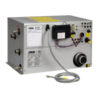
4. Release the 4 plate screws (g. 3A) securing the fan
to the fan housing.
5. Lift the fan out of the boiler body.
6. Fit the new fan by following these instructions in reverse.
NB! Take care not to damage the impeller when tting
the fan.
7. Ret the service panel and test-run the boiler.
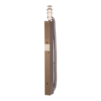
Fig 1.
B
H
F
E
G
C D
I
J
K
L
L
Fig 3.
B
A
B
A
A
CABLE MARKINGS FIG.1
1A Blue cable, marked Blue on the printed circuit board.
1B Brown cable, marked Brown on the printed circuit board.
1C Red cable, marked Red on the printed circuit board.
1D Grey cable, marked Grey on the printed circuit board.
1E Black cable, marked Black on the printed circuit board.
1F Blue cable from pump marked, PUMP-N on the
printed circuit board.
1G Brown cable from pump marked, PUMP-L on the
printed circuit board
1H White 6-point connection block from the sensors.
1I White 4-point connection block from fan.
1J White 5-point connection block from solenoid.
 Loading...