R0368
Cod.R0368‐rev.1.0
(03/2020)
Page 3/14
2 CONNECTIONS
2.1 Powerlineconnection
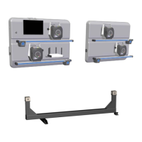
The alignment sensor panels must be connected to the 115/230Vac 50/60Hz power line; the maximum
powerusedis100W.
Usethepoweroutletlocatedonthesideofthepanels.
Thepanelscanbeconnectedtothenetworkseparately(ontwodifferentwalls)ortherightpanelcanbe
poweredonthepowerstripbehindtheleftpanel,asintheexampleinFigure3.
ATTENTION:Thepowerlineshouldnotbeturnedoffduringthenightasthedetectorsmustberecharged.
Figure3
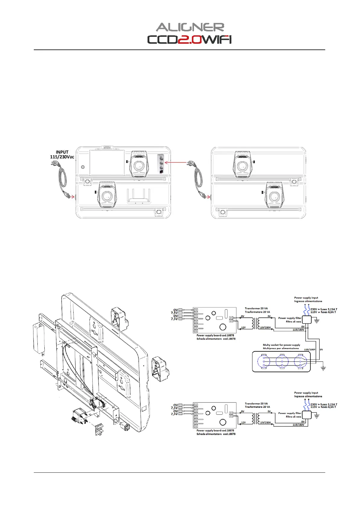
Thebatteriesofthedetectorsarerechargedwhentheyareplacedonthededicatedchargingsupportson
thepanel.Thesesupportscarry7.5VDCpowersupply.
Attention:The+/‐polesmustbecorrect,checkthemwhenthedetectorisbeingcharged.
Ifthe+/‐polesarecorrect,thebatteryischarged(thegreenLEDison);iftheyareinverteditwillNOTcharge.
Figure4showstheschematicdiagramsofthetwodetectorpanels.
Note:thepowersupplyboardofthechargingsupportscode18878has40/7.5Voutputs,butonly2areused.
Figure4
LEFT PANEL
RIGHT PANEL
 Loading...