Allen & Heath AP2794 issue 3 7
EXPANDER ASSIGNMENT
14. Depending on whether the expander is positioned on the left or right hand side of the main console, one or
more of the input connector circuit boards (AG2622) will have to be assigned to enable the channel mutes to
function correctly.
For consoles that have the expander on the right hand side of the console (e.g. expanded GL4000-824S and
GL4000-840S consoles) only the expander requires assignment.
For consoles that have the expander on the left hand side (e.g. expanded GL4000-832S consoles), all of the
input connector circuit boards will have to have the existing assignment links removed and re-assigned.
Refer to the assignment diagrams below.
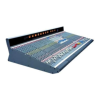
The assignment links are 0R resistors
‘Q’, located next to the 16 way ribbon harness connector on the
input connector circuit board. Fitting the links in various positions determines the assignment for each block
of 8 input channel mutes.
Link assignments for each input connector circuit board
To avoid having to remove the input connector circuit board, fit the links onto the track side of the circuit board
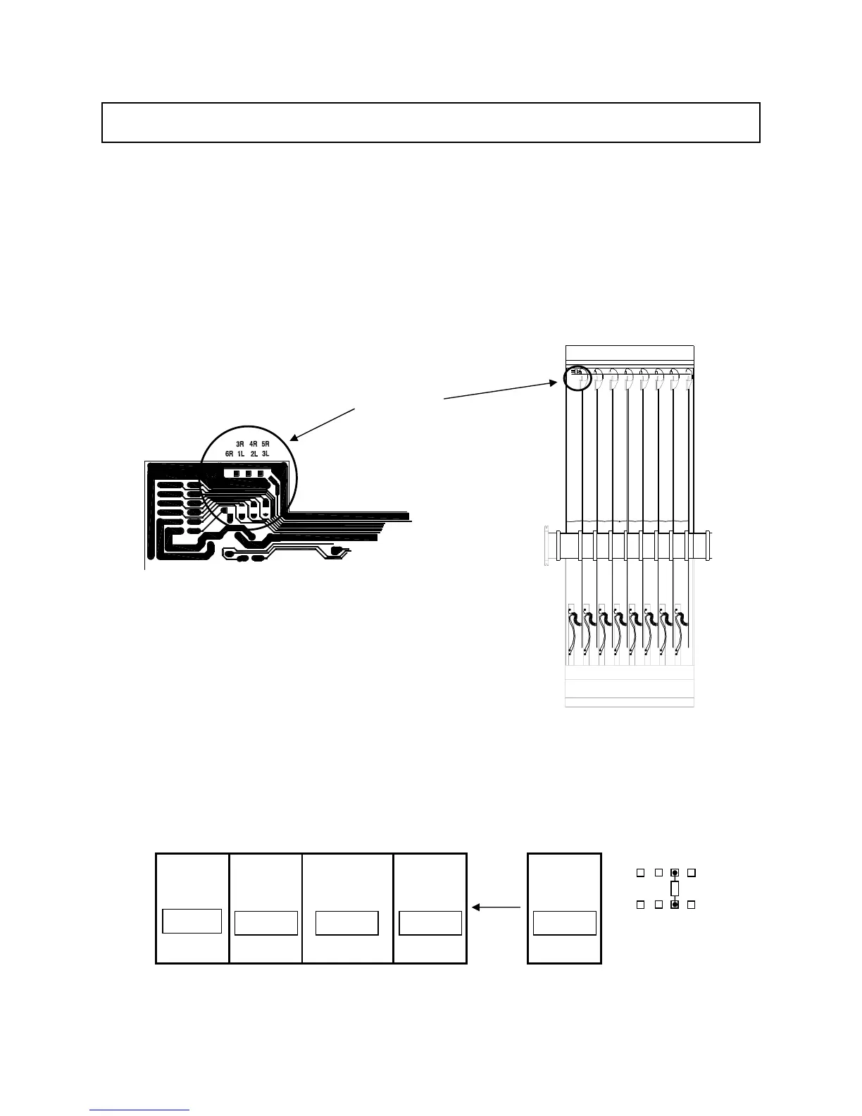
GL4000-824 + Expander
1 - 8
9 - 16 Master Expander17 - 24
3R 4R 5R
6R 1L 2L 3L
Trackside view
In
 Loading...