Creating Ladder Logic Programs 4–11
About the SLC Ladder Logic Program
About the SLC Display
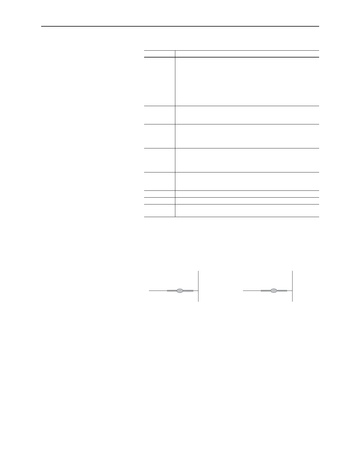
When you are creating an SLC ladder logic program, you can display
information by slot and bit or by slot, word, and bit.
Figure 4.5 SLC Displays
Rung Description
0001 When the machine Start push button is pressed, the SLC sends a START
command to the drive. The drive will start if no STOP command is being sent
by the SLC or any other control device. (Start button is a normally open
contact in this example.) SCANport products will start only if the start bit
transitions high while the stop bit is already low.
The address (O:1) is determined by the slot and word. It is displayed as a
continuous bit number. In the example, we use rack 02 and starting group
module word 0.
0002 When the machine Stop push button is pressed, the SLC sends a STOP
command to the drive. (Stop button is normally closed contact in this
example)
0003 A frequency command is transferred from the SLC data table to the drive. A
range of 0 to 32767 is equivalent to zero to maximum frequency. (In this
example, the drive frequency select parameters are set to receive a
frequency reference from the Remote I/O module.)
0004 When the machine Jog button is pressed, the SLC will send a JOG
command to the drive. The drive will start and run at the programmed jog
frequency if no STOP command is being sent by the SLC or other control
device. (Jog button is normally open contact in this example.)
0005 When the machine Clear Faults push button is pressed, the PLC sends a
CLEAR FAULTS command to the drive. (Clear Faults button is a momentary
normally open contact in this example.)
0006 When the drive is running, the SLC will receive a Drive Running status bit.
0007 When the drive is faulted, the SLC will receive a Drive Faulted status bit.
0008 A value is moved from the SLC data table into the drive parameter specified
by the Data In A1 parameter in the drive.
O:1.16
1
1747-SN
Drive
START
Command
O:1
257
1747-SN
Drive
START
Command
slot = 1
bit = 257
slot = 1
word = 16
bit = 1
Artisan Scientific - Quality Instrumentation ... Guaranteed | (888) 88-SOURCE | www.artisan-scientific.com

 Loading...


