FLEX I/O DC Input, Output, and Input/Output Analog Modules 7
Publication 1794-IN106D-EN-E - January 2014
Connect Wiring
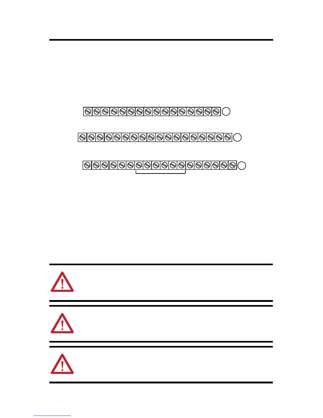
Connect the wiring for the 1794-TB3G and 1794-TB3GS terminal bases as shown in the
following figure:
Terminal Base Wiring for the 1794-IE12/A Analog Input Module
ATTENTION: To reduce susceptibility to noise, power analog modules and
digital modules from separate power supplies. Do not exceed a length of
10 m (33 ft) for DC power or analog I/O cabling.
ATTENTION: Do not daisy-chain power or ground from this terminal base
unit to any AC or DC digital module terminal base units.
ATTENTION: Do not exceed a length of 10 m (33 ft) for signal cabling.
I = Current [1794-TB3G shown]
V=Voltage
C-0...C-11 = Returns for I or V connections 0...11
+24V DC = Terminals C-34 and C-50
COM = Terminals C-35 and C-51
Chassis ground (CG) = Terminals B-16, B-33, C-38, C-40...C-45, C-47
NC = No connection
For daisy-chaining: Supply in – C-34 (+) and C-35 (-)
Supply out – C-50 (+) and C-51 (-)
24V DC
Supply In
24V DC
Supply Out
17 18 19 20 21 22 23 24 25 26 27 28 29 30 31 32 33
0 1 2 3 4 5 6 7 8 9 10 11 12 13 14 15
16
35 36 37 38 39 40 41 42 43 44 45 46 47 48 49 50 51
34
Chassis
Ground
Chassis
Ground
+V COM +V COM
Chassis Grounds for Shields
A
B
C
NC
I0 I1 I2 I3 I4 I5 I6 I7
I8 I9 I10 I11
V0 V1 V2 V3 V4 V5 V6 V7
V8 V9 V10 V11C0 C1 C2 C3 C4 C5 C6 C7
C8 C9 C10 C11NC
NC NC
 Loading...


