8 Rockwell Automation Publication 2080-UM004C-EN-E - March 2015
Chapter 2 Install and Wire Your Module
1. Position the plug-in module with the terminal block facing the front of the
controller as shown.
2. Snap the module into the module bay.
3. Using a screwdriver, tighten the 10…12 mm (0.39…0.47 in.) M3 self
tapping screw to torque specifications.
See Specifications
on page 59 for torque specifications.
Wiring
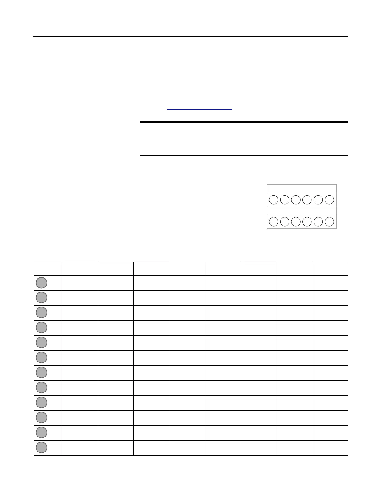
The following plug-in modules have 12-pin
female terminal blocks:
• 2080-IQ4,
• 2080-IQ4OB4, 2080-IQ4OV4
• 2080-OB4, 2080-OV4, 2080-OW4I
• 2080-IF2, 2080-IF4
• 2080-TC2, 2080-RTD2
Analog I/O performance depends on the application. For better noise
immunity, cable length should ideally be less than 10 m because the
plug-ins are non-isolated. For longer cable length requirements, use the
2085 expansion I/O modules instead.
1 2 3 4
1 2 3 4
5 6
5 6
Back
A
B
Front
Twelve-pin Female Terminal Block
Pin Designations for 12-Pin Female Terminal Block Modules
Pin 2080-IQ4 2080-IQ4OB4,
2080-IQ4OV4
2080-OB4,
2080-OV4
2080-OW4I 2080-IF2 2080-IF4 2080-TC2 2080-RTD2
I-02 I-02 Not used COM3 COM COM CH0+ CH0+
I-03 I-03 Not used O-3 Not used VI-2 CH0- CH0-
COM COM -24V DC Not used Not used CI-2 CJC+ CH0L (Sense)
COM -24V DC -24V DC Not used COM COM Not used Not used
Not used O-02 O-02 Not used Not used VI-3 Not used Not used
Not used O-03 O-03 Not used Not used CI-3 Not used Not used
I-00 I-00 Not used COM0 VI-0 VI-0 CH1+ CH1+
I-01 I-01 Not used O-0 CI-0 CI-0 CH1- CH1-
COM COM +24V DC COM1 COM COM CJC- CH1L (Sense)
COM +24V DC +24V DC O-1 VI-1 VI-1 Not used Not used
Not used O-00 O-00 COM2 CI-1 CI-1 Not used Not used
Not used O-01 O-01 O-2 COM COM Not used Not used
 Loading...
