Home
Allen-Bradley
Control Unit
POINT I/O series
Allen-Bradley POINT I/O series User Manual
5
of 1
of 1 rating
24 pages
Give review
Manual
Specs
To Next Page
To Next Page
To Previous Page
To Previous Page
Loading...
10
PO
INT I/O 2 an
d 4 Relay Ou
tput Modul
es
Publica
tion 1734
-IN055H-
EN-E - Au
gust 2016
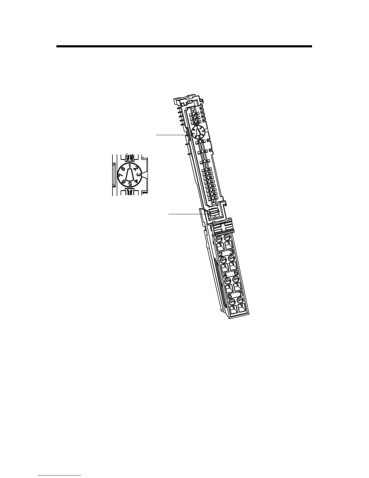
3.
Inser
t
the m
o
du
le s
tra
ig
ht
down
into
the
mo
unting
ba
se
an
d pre
ss t
o se
c
ure.
The mo
dule lo
cks into place.
T
urn the keyswitch
to align the
number with the no
tch.
Notch position 3
is shown.
Make sure the DIN
rail locking
screw is in the horizontal position.
1734-TB Base
45696
9
11
Table of Contents
Table of Contents
1
Important User Information
2
Environment and Enclosure
3
Preventing Electrostatic Discharge
3
North American Hazardous Location Approval
4
European Hazardous Location Approval
5
About the Module
6
Mount the I/O Base
8
Install the Module
9
Install the Removable Terminal Block
12
Remove a Mounting Base
14
Communicate with Your Module
14
Wire the Module
15
Interpret Status Indicators
19
Specifications
21
5
Based on 1 rating
Ask a question
Give review
Questions and Answers:
Need help?
Do you have a question about the Allen-Bradley POINT I/O series and is the answer not in the manual?
Ask a question
Allen-Bradley POINT I/O series Specifications
General
Brand
Allen-Bradley
Model
POINT I/O series
Category
Control Unit
Language
English
Related product manuals
POINT I/O 1734-232ASC
74 pages
POINT I/O PROFIBUS 1734-APB
88 pages
Allen-Bradley FLEX I/O 1794-OB8
28 pages
FLEX I/O ControlNet D Series
6 pages
Allen-Bradley PowerMonitor 500
90 pages
ProcessLogix B Series
36 pages
ProcessLogix 1757 Series
120 pages
Allen-Bradley POINT I/O
118 pages
POINT I/O 1734-AENT
24 pages
Allen-Bradley 1756
42 pages
Allen-Bradley Series B
132 pages
Allen-Bradley 1756 Series
136 pages
 Loading...