Publication 20D-IN027A-EN-P
2
Before proceeding, ensure that all power to the drive has been removed.
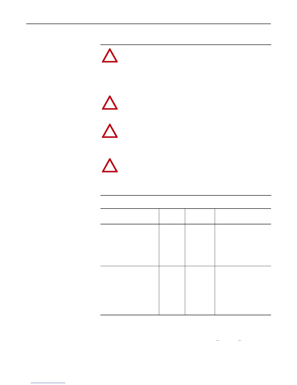
Table A Recommended Power Jumper Configurations
To connect or disconnect these devices, refer to pages 4 through 7.
!
ATTENTION: This drive contains ESD (Electrostatic Discharge)
sensitive parts and assemblies. Static control precautions are required
when installing, testing, servicing or repairing this assembly.
Component damage may result if ESD control procedures are not
followed. If you are not familiar with static control procedures,
reference A-B publication 8000-4.5.2, Guarding Against
Electrostatic Damage or any other applicable ESD protection guide.
!
ATTENTION: Only qualified personnel familiar with adjustable
frequency AC drives and associated machinery should perform
maintenance/repair of the system. Failure to comply may result in
personal injury and/or equipment damage.
!
ATTENTION: To avoid an electric shock hazard, verify that the
voltage on the bus capacitors has discharged before performing any
work on the drive. Measure the DC bus voltage at the +DC & –DC
terminals of the Power Terminal Block (refer to the User Manual for
location). The voltage must be zero.
!
ATTENTION: The following information is merely a guide for
proper installation. Rockwell Automation cannot assume
responsibility for the compliance or the noncompliance to any code,
national, local or otherwise for the proper installation of this drive or
associated equipment. A hazard of personal injury and/or equipment
damage exists if codes are ignored during installation.
Power Source Type
(1)
(1)
It is highly recommended to accurately determine the power source type and then configure appropriately.
MOV/Input
Filter Caps
(2)
(2)
When MOVs are disconnected, the power system must have its own transient protection to ensure known and
controlled voltages.
DC Bus
Common Mode
Caps
Benefits Of Correct
Configuration on Power Source
Type
Solid Ground
• AC fed, solidly grounded
• DC fed from passive rectifier
which has an AC source and
solid ground
Connected Connected • UL compliance,
• Reduced electrical noise,
• Most stable operation,
• EMC compliance,
• Reduced voltage stress on
components and motor
bearings
Non-Solid Ground
• AC fed ungrounded
• Impedance grounded
• High resistive ground
• B phase ground
• Regenerative unit such as
common DC bus supply & brake
• DC fed from an active converter
Disconnected Disconnected • Helps avoid severe equipment
damage when ground fault
occurs

 Loading...


