Rockwell Automation Publication 750-PC100A-EN-P - December 2016
PowerFlex 750-Series Products with TotalFORCE Control 25
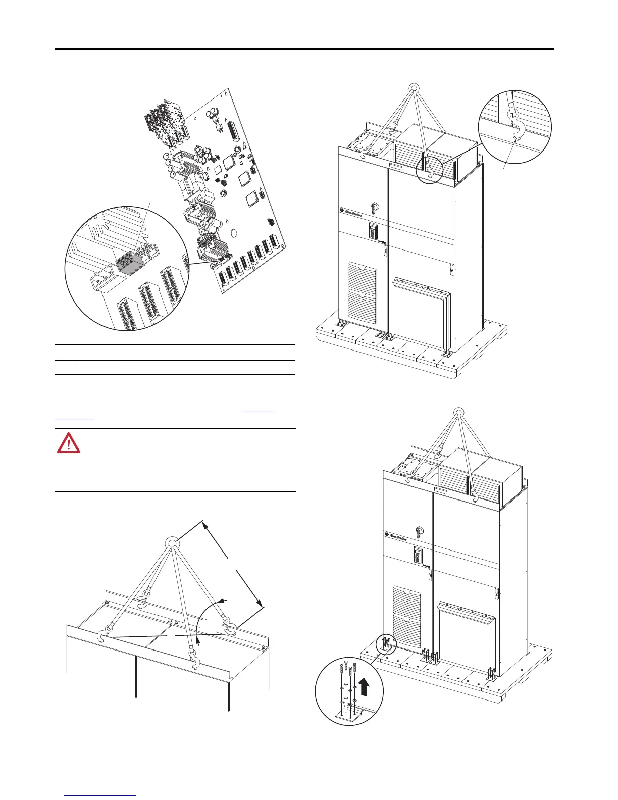
Fiber Interface Board Details
Lift the Equipment
All lifting equipment and lifting components (hooks, bolts, lifts, slings, chains, and so forth) must be properly
sized and rated to safely lift and hold the weight of the equipment while mounting. See Approximate
Weights on page 3.
Attach Lifting Hardware
Rig the lifting hardware according to the following diagram.
Typical Lifting Points
Release Cabinet From Shipping Skid
Remove the lag bolts that fasten the cabinet cleats to the shipping skid and lift.
Item Name Description
1 Connector J13 Connection for terminal block P13 - optional external 24V DC power supply.
ATTENTION: To guard against possible personal injury and/or equipment damage…
• Inspect all lifting hardware for proper attachment before lifting equipment.
• Do not allow any part of the equipment or lifting mechanism to make contact with electrically
charged conductors or components.
• Do not subject the equipment to high rates of acceleration or deceleration while transporting
to the mounting location or when lifting.
• Do not allow personnel or their limbs directly underneath the equipment when it is being lifted
and mounted.
Ø40 mm
(1.4 in.)

 Loading...


