2 PowerFlex® DC Drive - Frame A Switching Power Supply Circuit Board
What You Need to Do
To install the Switching Power Supply board:
❐ Step 1: Remove power from the drive
❐ Step 2: Remove the protective covers
❐ Step 3: Remove the Control EMI Shield and Control board
❐ Step 4: Remove the existing Pulse Transformer and Switching Power
Supply boards
❐ Step 5: Install the existing Pulse Transformer board and new
Switching Power Supply board
❐ Step 6: Install the Control EMI Shield and Control board
❐ Step 7: Replace the protective covers and document the change
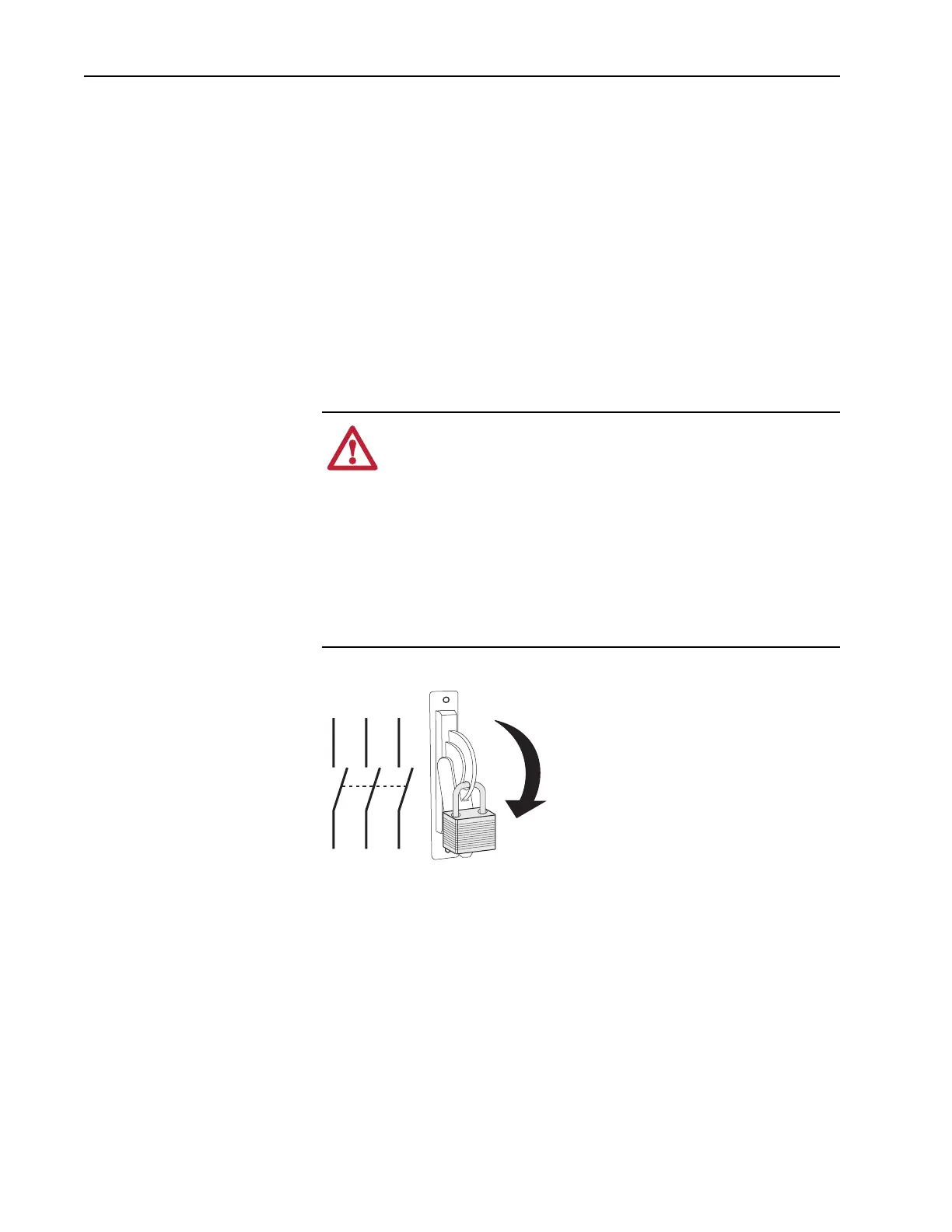
Step 1: Remove Power
from the Drive
1. Remove and lock-out all incoming power to the drive.
ATTENTION: Remove power before making or breaking cable
connections. When you remove or insert a cable connector with
power applied, an electrical arc may occur. An electrical arc can
cause personal injury or property damage by:
• sending an erroneous signal to your system’s field devices,
causing unintended machine motion
• causing an explosion in a hazardous environment
Electrical arcing causes excessive wear to contacts on both the
module and its mating connector. Worn contacts may create
electrical resistance.
L1 L2 L3
O
I

 Loading...


