48 Rockwell Automation Publication PFLEX-AP005B-EN-P - May 2019
Chapter 1 Drive Selection Considerations
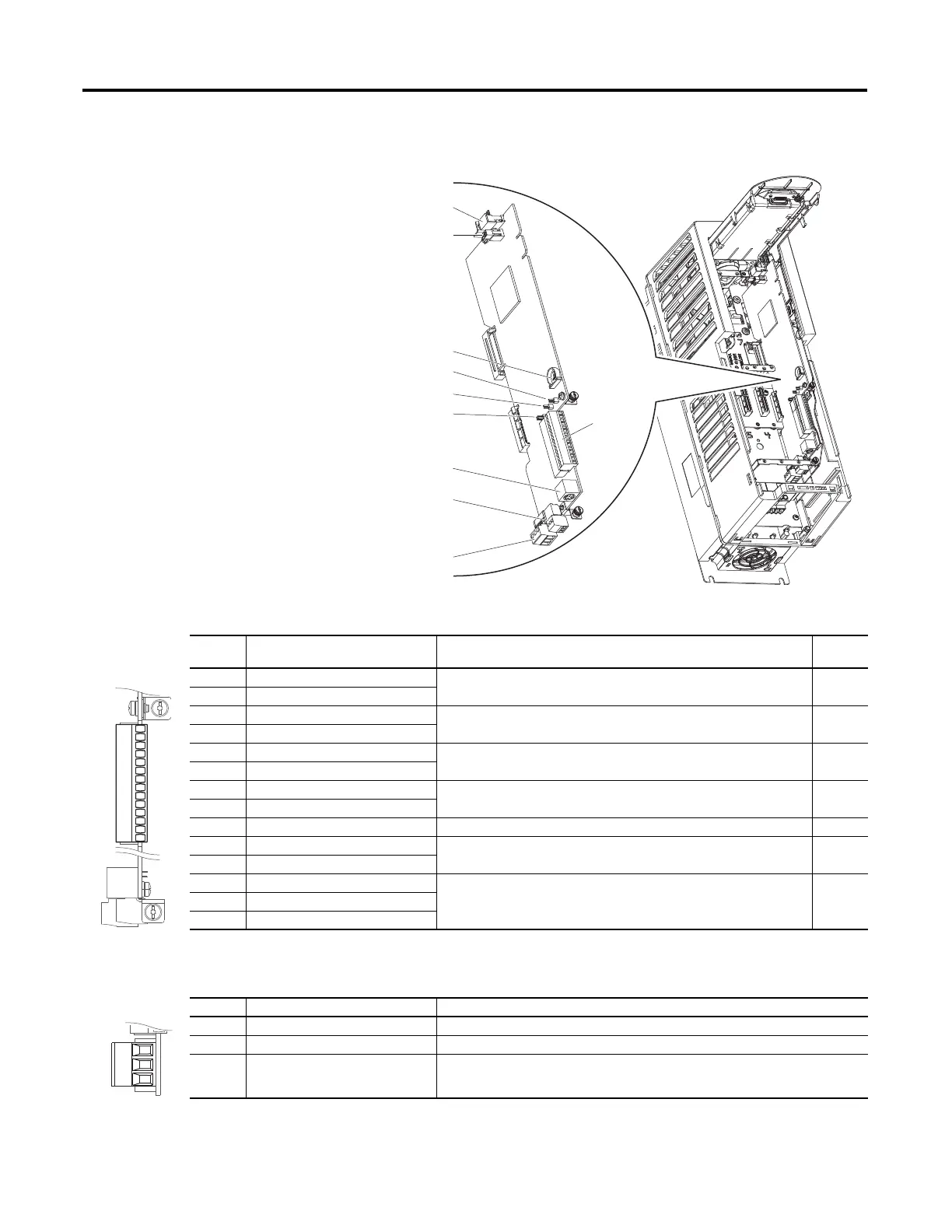
PowerFlex 753 Drives Main Control Board I/O
Table 26 - PowerFlex 753 Drive TB1 Terminal Designations
Table 27 - PowerFlex 753 Drive TB2 Terminal Designations
TB1
HIM Connector
Fan Connector
Battery Receptacle
J1 ENABLE Jumper
J2 SAFETY Jumper
J4 Input Mode Jumper
DPT Port 2
TB3
TB2
Terminal Name Description
Related
Param
Ao0– Analog Out 0 (–) Bipolar, ±10V, 11 bit and sign, 2 kohm minimum load;
4
…20 mA, 11 bit and sign, 400 ohm maximum load
270
Ao0+ Analog Out 0 (+)
10VC 10 Volt Common For (+) 10 Volt references;
2 kohm minimum
+10V +10 Volt Reference
Ai0– Analog Input 0 (–) Isolated
(1)
, bipolar, differential, ±10V, 11 bit and sign, 88 kohm input
impedance
255
Ai0+ Analog Input 0 (+)
Ptc– Motor PTC (–) Motor protection device
(Positive Temperature Coefficient)
250
Ptc+ Motor PTC (+)
T0 Transistor Output 0 Open drain output, 48V DC 250 mA maximum load
24VC 24 Volt Common Drive supplied logic input power;
150 mA maximum
+24V +24 Volt DC
Di C Digital Input Common 24V DC - Opto isolated
Low State: less than 5V DC
High State: greater than 20V DC
150
Di 1 Digital Input 1
Di 2 Digital Input 2
(1) Differential Isolation—external source must be maintained at less than 160V with respect to PE. Input provides high common mode immunity.
Ao0-
Ao0+
10VC
+10V
Ai0-
Ai0+
Ptc-
Ptc+
To 0
24VC
+24V
Di C
Di 1
Di 2
Terminal Name Description
R0NC Relay 0 N.C. Output Relay 0 normally closed contact
R0C Relay 0 Common Output Relay 0 common
R0NO Relay 0 N.O. Output Relay 0 normally open contact

 Loading...


