Rockwell Automation Publication 1783-IN022A-EN-P - July 2023 14
Stratix 5200 Ethernet Managed Switches Installation Instructions
Connect to 10Base-T, 100Base-TX, or 1000Base-T Ports
To connect to 10Base-T, 100Base-TX, or 1000Base-T ports, follow these steps.
1. To connect a device, choose one of the following options:
• When connecting to workstations, servers, and routers, connect a straight-through cable to an RJ45 connector on the front panel.
• When connecting to 1000Base-T-compatible devices, use a twisted four-pair, Category 5e or higher cable.
2. Connect the other end of the cable to an RJ45 connector on the other device.
The port status indicator turns on when both the switch and the connected device have an established link.
The port status indicator is amber while Spanning Tree Protocol (STP) discovers the topology and searches for loops. This can take up to 30 seconds, and then the Port
status indicator turns green.
The following conditions can help prevent the port status indicator from turning On:
• The device at the other end is not turned On.
• A problem exists with a cable or the adapter that is installed in the attached device.
3. Reconfigure and restart the connected device if necessary.
4. To connect each device, repeat this procedure.
Confirm Installation
To confirm the installation, power on the switch, and verify that the switch powers up. The time that is required for the switch to startup is directly related to your switch
configuration. Start time is negatively affected by such things as the following:
• Spanning Tree Learning mode
• Number of files or images in onboard memory
To test the switch, follow these steps.
1. Apply power to the switch.
If the switch is directly connected to a DC power source, locate the circuit breaker on the panel board that services the DC circuit, and switch the circuit breaker to the On
position.
2. Verify the startup sequence.
When you power on the switch, it begins a startup routine. The Setup status indicator blinks green as the IOS software image loads. If the routine fails, the Setup status
indicator turns red.
3. After successfully running this test, do the following:
a. Turn off power to the switch.
b. Disconnect the cables.
c. Decide where you want to install the switch
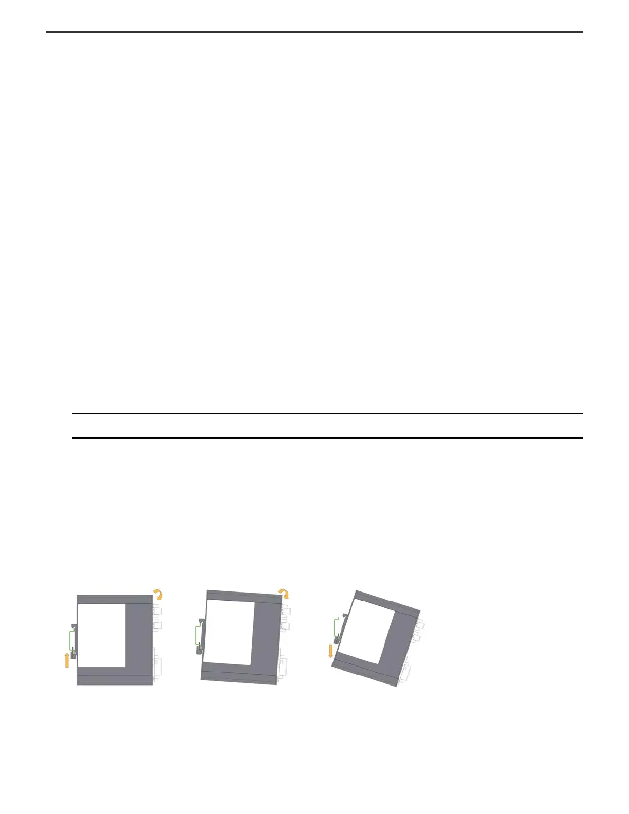
Remove the Switch from the DIN Rail
Remove power from the switch, and disconnect all cables and connectors from the front panel of the switch. Use the following steps to remove the switch from a DIN rail or rack.
1. To compress the spring in the DIN rail clip, press up on the switch.
2. Grasp the upper part of the switch and rotate it away from the DIN rail.
3. Lower the switch away from the DIN rail and remove it.
IMPORTANT Startup failures are fatal to the switch. Contact your Rockwell Automation representative immediately if your switch does not complete the start
sequence successfully.
 Loading...


