EasyManua.ls Logo

ALLIANCE SWNNC2SP115TW02 User Manual

ALLIANCE SWNNC2SP115TW02
90 pages
To Next Page IconTo Next Page
To Previous Page IconTo Previous Page
Page #73 background imageLoading...
Page #73 background image
Diagnostic Test Descriptions
Control Software Version Number Test d 1
This option displays the control software version number. To start
test, control must be in the Testing Mode. Refer to How to Enter
Testing Feature at the beginning of this section.
To enter, press the START (enter) keypad. The display will show
S XX where XX is the software version number.
To exit the Software Version Number Test, press the WARM (<)
keypad. The control will return to the Testing Mode.
Input/Output Software Version # Test d 2
This option displays the drive board software version number. To
start test, control must be in the Testing Mode. Refer to How to
Enter Testing Feature at the beginning of this section.
To enter, press the START (enter) keypad. The display will show
ob XX where XX is the software version number.
To exit the Drive Board #1 Version Test, press the WARM (<)
keypad. The control will return to the Testing Mode.
Service Door Opening Test d 8
This option tests the service door switch. To start test, control
must be in the Testing Mode. Refer to How to Enter Testing Fea-
ture at the beginning of this section.
To enter, press the START (enter) keypad. The display will show
S oP when the service door switch is open and S CL when the
service door switch is closed.
The service door switch has to be closed for at least one second
and opened for at least one second for the display to change. This
test will add a count to the service door opening counter for the
audit and save the date/time for each opening.
To exit the Service Door Opening Test, press the WARM (<) key-
pad. The control will return to the Testing Mode.
Coin Vault Opening Test d 9
This option tests the coin vault switch. To start test, the control
must be in the Testing Mode. Refer to How to Enter Testing Fea-
ture at the beginning of this section.
To enter, press the START (enter) keypad. The display will show
v oP when the coin vault switch is open and v CL when the
coin vault switch is closed.
The coin vault switch has to be closed for at least one second and
opened for at least one second for the display to change. This test
will add a count to the coin vault opening counter for the audit
and save the time/date for each opening.
To exit the Coin Vault Opening Test, press the WARM (<) key-
pad. The control will return to the Testing Mode.
Coin Drop 1 Input Test d 10
This option tests coin drop #1. To start test, control must be in the
Testing Mode. Refer to How to Enter Testing Feature at the be-
ginning of this section.
To enter, press the START (enter) keypad. The display will show
C1 XX. The XX will show the number of coins entered and will
increment one for each coin entered in coin drop #1.
NOTE: Coins entered in test mode will not increment
the total # of coins counter that is accessed in the audit
feature.
To exit the Coin Drop #1 Input Test, press the WARM (<) key-
pad. The control will return to the Testing Mode.
Coin Drop 2 Input Test d 11
This option tests coin drop #2. To start test, control must be in the
Testing Mode. Refer to How to Enter Testing Feature at the be-
ginning of this section.
To enter, press the START (enter) keypad. The display will show
C2 XX. The XX will show the number of coins entered and will
increment one for each coin entered in coin drop #2.
NOTE: Coins entered in test mode will not increment
the total # of coins counter that is accessed in the audit
feature.
To exit the Coin Drop #2 Input Test, press the WARM (<) key-
pad. The control will return to the Testing Mode.
Vend Connection Header Present Test d 12
This option tests the vend header connection. To start test, control
must be in Testing Mode. Refer to How to Enter Testing Feature
at the beginning of this section.
To enter, press the START (enter) keypad. The display will show
CH oP when the wiring connection is open and CH CL when the
connection is closed.
To exit Vend Connection Header Present Test, press the WARM
(<) keypad. The control will return to the Testing Mode.
Start Pulse Test d 13
This option tests the Start Pulse. To start test, control must be in
the Testing Mode. Refer to How to Enter Testing Feature at the
beginning of this section.
To enter, press the START (enter) keypad. The display will show
St XX. The XX will show the number of pulses entered. This test
will add counts to the total number of Start Pulses counter. Refer
to Collecting Audit Information.
To exit the Start Pulse Test, press the WARM (<) keypad. The
control will return to the Testing Mode.
Lid Switch Input Test d 15
This test will display whether the washer lid is open or closed.
Testing Machine and Electronic Control Functions
©
Copyright, Alliance Laundry Systems LLC -
DO NOT COPY or TRANSMIT
73 Part No. 204370ENR1

Table of Contents

Question and Answer IconNeed help?

Do you have a question about the ALLIANCE SWNNC2SP115TW02 and is the answer not in the manual?
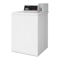
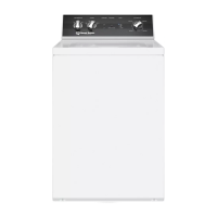
ALLIANCE SWNNC2SP115TW02 Specifications

General IconGeneral
BrandAlliance
ModelSWNNC2SP115TW02
Voltage120V
PhaseSingle Phase
Loading TypeTop Loading
TypeWasher
Control TypeElectronic

Summary

Topload Washer Operation Manual

Programming and Control Overview

Overview of the control interface and general programming capabilities of the topload washer.

Safety and Important Warnings

General Safety Instructions

Crucial information for safe installation, maintenance, and operation of the washer.

Model Identification

Preliminary Information and Communication

About the Control System

Overview of the advanced programmable computer control for the washer.

Glossary of Terms

Definitions of key terms and abbreviations used in the manual.

Power Failure Recovery

How the washer recovers operation after a power interruption.

Communication Methods

Methods for programming and data retrieval via external devices.

Control Panel Identification

Control Pads and Buttons

Details on cycle, temperature, and modifier selection pads.

Display Elements

Description of 7-segment digits and LEDs.

Display and Indicator Identification

Light Emitting Diodes (LEDs)

Explains the function of various LEDs indicating cycle status and selections.

7-Segment Digital Display

Describes the use of digital displays for time, price, and error messages.

Basic Washer Operation

Power Up and Ready Mode

Initial state and readiness for operation.

Vend Modes and Start Procedure

Partial/additional vend modes and starting the cycle.

Cycle Sequence and Signals

How the control indicates cycle progress and uses signals.

Washer Lid Operation

How opening the lid affects cycle operation.

Advanced Operation Modes

Changing Cycles and Delayed Start

How to modify cycles and set delayed starts.

Special Operational Modes

Overflow, Lockout, and Shutdown modes.

Power Failure Handling

Power Failure Display Mode

Indicates an interrupted cycle due to power failure.

Special Features Overview

Programming and Audit Features

Control programming, audit information retrieval.

Diagnostic and Special Functionality

Testing, rapid advance, clear vend, communications.

Payment and Access Features

Coin drop, start pulse, service door access.

Additional Special Features

Security and Operational Modes

Break-in alarm, OPL, Drop-Off, Out of Order modes.

Special Vend and Power Management

Special vend pricing, low power/auto-shutdown.

Error and Network Display Modes

Network node and error display modes.

Service Door Access Procedures

Opening the Service Door

Procedure to open the service door for programming and diagnostics.

Manual Mode Operations

Entering Manual Mode

Step-by-step guide to enter Manual Mode for programming and testing.

Manual Mode Navigation Structure

Overview of the five groups within Manual Mode.

Programming Control Details

Programmable Options Overview

List and description of all available programming options.

Vend Price Programming

Setting Base Vend Prices (1-4)

Setting vend prices for different cycles and temperatures.

Advanced Vend Price Settings

Setting Vend Prices (5-8)

Setting vend prices for different cycles and temperatures.

Modifier and Decimal Point Settings

Cycle Modifier Price Adders

Adding prices to MEDIUM/HEAVY modifier keys.

Vend Price Decimal Point Configuration

Option to show decimal points in vend price display.

Coin and Start Pulse Configuration

Coin Value Settings

Configuring coin values for vend price calculation.

Start Pulse Settings

Configuring start pulse parameters for payment systems.

Output Type and Signal Configuration

Programmable Output Type

Programming control outputs for various reasons.

Signal Availability Modes

Defining when signals are active based on output type.

Cycle and Communication Settings

Default Cycle Selection

Setting the default cycle upon machine startup.

Card Reader and Audio Signal Settings

Configuring card reader display and audio signals.

Network and Error Code Configuration

Network Node Number Setup

Programming a unique number for wired/wireless communication.

Error Code Management

Enabling or disabling specific error codes.

Time and Special Vend Management

Real-Time Clock and Daylight Savings

Setting the internal clock and daylight savings.

Special Vend Days Enable

Enabling or disabling Special Vend 1 for specific days.

Special Vend and Cycle Modifier Configuration

Special Vend Days Enable (2-4)

Enabling/disabling Special Vends 2, 3, and 4 for specific days.

Cycle Modifier Programming

Programming extra time for wash, rinse, or warm rinse.

Default Cycle Modifier Setting

Setting the default cycle modifier for Ready Mode.

Cycle Modifier Time Adjustments

Modifier Options and Time Additions

Configuring options and adding time for MEDIUM/HEAVY modifiers.

Cycle Parameters and Power Management

Cycle Parameters Configuration

Setting time for various steps in different cycles.

Low Power/Auto-Shutdown Settings

Enabling low power/shutdown for specific days of the week.

Power Failure and System Access

Power Fail Reset Configuration

Setting time to store cycle info during power failure.

IR Access and Manual Mode Enable

Enabling/disabling IR communication and manual modes.

Diagnostic and Test Mode Access

Manual Rapid Advance and Diagnostics

Enabling/disabling rapid advance and manual diagnostics.

Factory Test Mode Access

Enabling or disabling access to factory test mode.

Special Cycle and Display Features

Lucky Cycle and Water Temperature

Configuring lucky cycles and water temperature indicator.

Programmable Lid Display Settings

Enabling/disabling display of close lid command.

Display and OPL Parameter Configuration

Programmable Display Options

Settings for push start and open lid display commands.

Vend Price Override and OPL Parameters

Overriding vend price and configuring OPL parameters.

OPL Mode and Drop-Off Configuration

OPL Delayed Start and Power Save

Enabling delayed start and power saving for OPL mode.

Drop Off Mode Setup

Setting up drop-off mode for attendant use without vend.

Out of Order Mode

Out of Order Mode Configuration

Disabling machine use with an out-of-order message.

Audit Information Retrieval

Accessing and Reading Audit Data

Methods to access and view audit feature data.

Manual Reset Procedure

Entering Manual Reset

Steps to reset control to factory default settings.

Diagnostic Testing Procedures

Entering and Starting Diagnostic Tests

Steps to enter and start diagnostic tests.

Exiting Diagnostic Tests

How to end diagnostic tests.

Detailed Diagnostic Test Descriptions

Software Version and Switch Tests

Testing software versions and door/vault switches.

Coin Drop, Vend, Pulse, and Lid Tests

Testing coin drops, vend connection, start pulse, and lid switch.

Fill/Drain Time and Related Tests

Testing fill/drain times and related operations.

Water and Output Diagnostic Tests

External Outputs and Water Purge Tests

Testing external outputs and water purge functionality.

Water Leak Detection and Level Tests

Testing for water leaks and displaying water level sensor readings.

Configuration Display Tests

Machine Configuration Display

Displaying machine configuration values and dipswitch settings.

Factory Test Procedures

Accessing and Exiting Factory Test

Steps to enter and exit the factory test mode.

Factory Test Quick Reference

Quick reference chart for factory test modes and displays.

Troubleshooting Error Codes

External Device Communication Errors

Errors related to Infra-red and card reader communication.

Machine and Payment System Errors

Errors related to machine operation and payment systems.

General Machine Error Codes

Codes for common machine errors like communication or configuration issues.

Specific Machine Error Codes

Communication and Configuration Errors

Codes for errors like no communication, mismatches, or brownouts.

Water Leak and Drain Error Codes

Codes for water leak and drain detection issues.

Advanced Machine Error Codes

Data Integrity and Communication Errors

Codes for corrupted data, control configuration, and board communication.

Drain, Slow Drain, and Water Leak Errors

Codes for drain, slow drain, and water leak detection issues.

Protection and System Error Codes

Overflow and Pressure Sensor Errors

Codes for overflow and pressure sensor issues.

Thermal Protect and Board Errors

Codes for motor thermal protection and drive/output board issues.

Default Cycle Time Configuration

Default Cycle Steps and Durations

Details the default cycle steps and durations programmed at the factory.

Related product manuals